KTM e-SXF 2009 in the French Alps

Gregzouz

1 mW
Joined
Nov 15, 2023
Messages
19
Location
Saint Joseph de Riviere
Hello everybody,

I'm Greg from French Alps.
I come to this forum to present to you my build project based on a dirty KTM 450 SXF from 2009 bought 900€ without motor.

The swap consist of :
- motor QS138 70H V3 with installation of the 3SHUL encoder kit

- ESC 3SHUL CL700

- DOMINO throttle

- homemade battery build with :
* NMC Li-Ion cells from CALB with threaded studs on copper 60mm² bus bars
* 89 V nominal (24S1P)
* 58 Ah
* 5150 Wh
* 110 A continuous
* 350 A peak
* ANT BMS
* aluminium plates casing

- RAGE MECHANICS Smart Display

- CHARGERY POWER charger

I'm a mechanical engineer so for the dismantling, cleaning, rebuild, optimizing steps, no problem even for adaptation of motor or battery mounts on the steel frame.

Here is the bike in puzzle mode before treatment on parts :
20220822_161234.jpg

Mechanic is well advanced and I post the before/after of the front brake to give you an example of what finition I intend (more photo available if wanted by the crew) :
Etrier avant.jpg

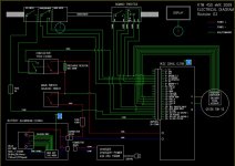
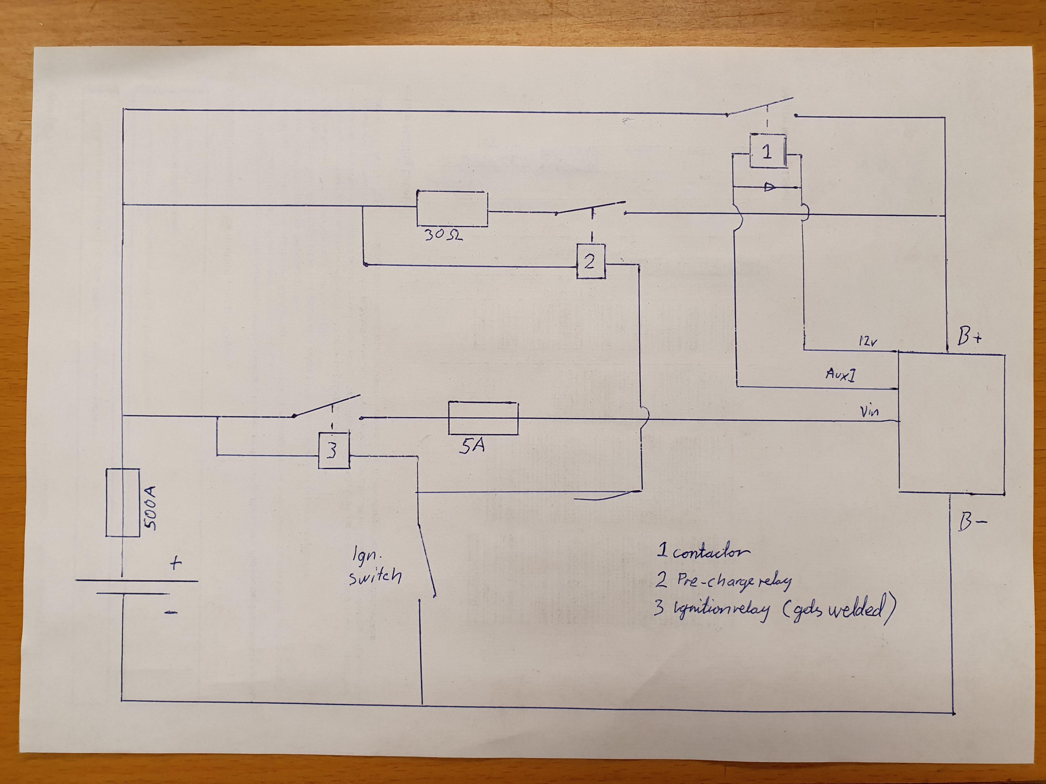
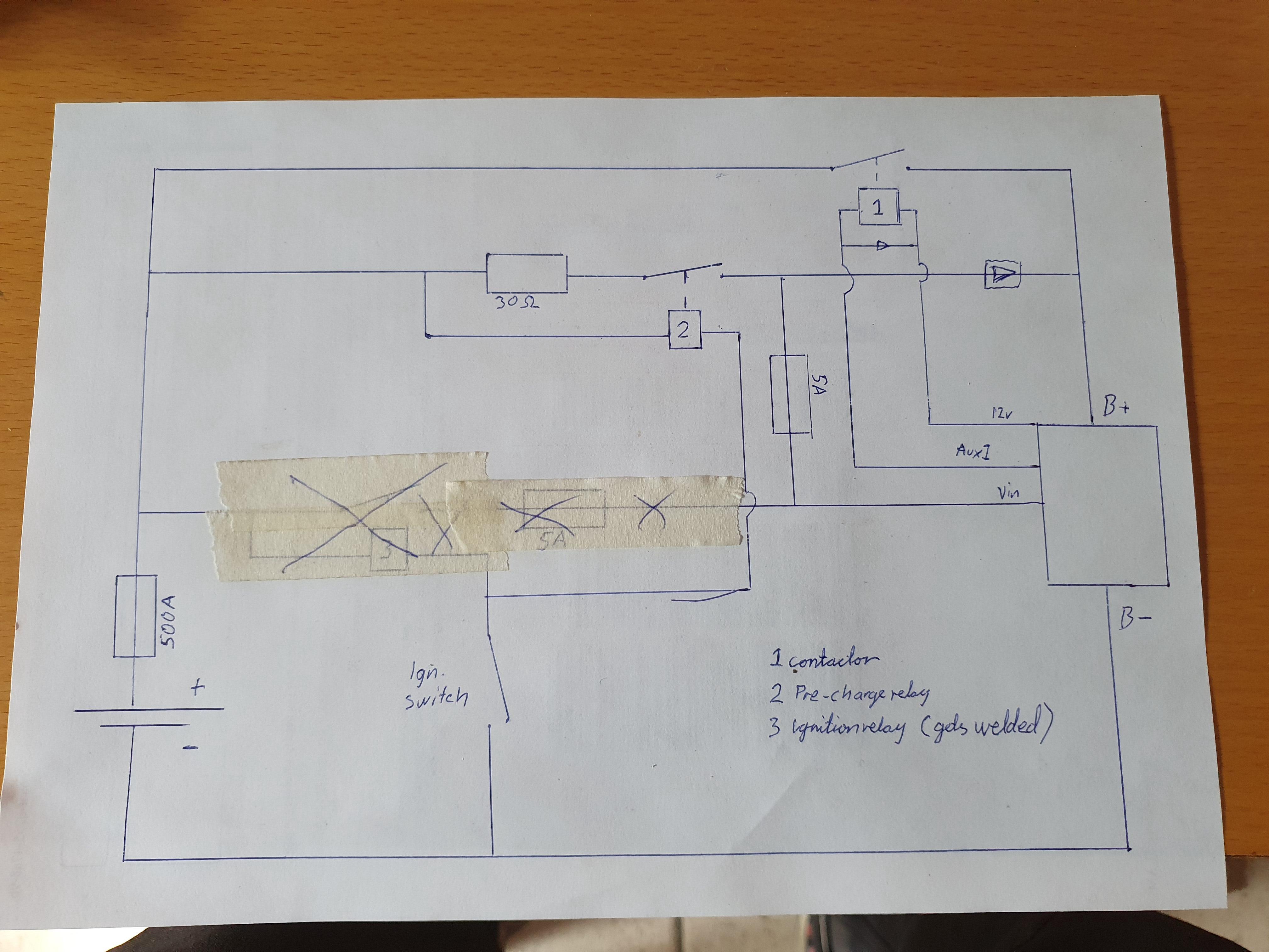
But before asking to you a LLLOOOOTTT of questions about setting the BMS/ESC of my installation, I still need some advice, comment and/or confirmation about the main electrical scheme of the bike. My last version is below :
Logigramme_07_EN.png

What do you think. I have already removed the back EMF diode on ESC inputs cause Hackey BABEL from 3SHUL told me this is not necessary. I'm wondering how to remove the DC converter 12V to have something more reliable and simplier but how to ignit the beast without any fire risk !!! ? 😅
And I still wait assembly instructions from Hackey for the installation of the encoder kit inside the motor. If someone has a link or done the work with pictures or videos, I'm quite interested !!!

Thanks for your advices/comments/congratulations/threat messages ! I take everything to have a perfect bike with mainly range but also some punch and reliability to go back home with smile and dirt-covered-teeth after each session in the woods around !
 
Last edited:
The controller has a built in 12v converter, so an external just to control the contactor isnt really necessery. It will start to give out power when you connect the "ignition" or what it is called. I would go for the cl1000 instead, I suppose 700pA is max (where it trips overcurrent) so 5-600 is what you can run on the cl700.
 
The controller has a built in 12v converter, so an external just to control the contactor isnt really necessery. It will start to give out power when you connect the "ignition" or what it is called. I would go for the cl1000 instead, I suppose 700pA is max (where it trips overcurrent) so 5-600 is what you can run on the cl700.
OK, I know that 12V is supplied by VESC. But if I understand well, if the controller is not supplied through main switch/contactro, no 12V available so no possibility to command the contactor. I'm afraid to not understand in fact.
Anyway I'm glad that someone like you who build dream bikes can see my project. Maybe it's too much, but do you have some general electrical diagram of your YZ and/or EXC ? I could just copy the principle and adpat to my bike if you agree.
 
Also, by discussing with Mike Reinalda who got informations from Lee Underwood, I have schematized something like this to eliminate DC converter (it's based on a magnificient paper drawing from Lee ! :ROFLMAO:) :
Logigramme_08_EN.png
But I was even thinking tu eliminate the momentary switch and have something like this :
Logigramme_09_EN.png

What do you think guys ?
 
I dont have any nice computer drawn diagrams, but there are some descriptions and drawings on paper in my yamaha thread. Basically it works like your revision 8, but where you have the main switch I have the contactor that is controlled by the 3shul.
Where you have the momentary switch I have a relay that is controlled by a switch, when that relay turns on it also turn on the ignition input on the 3shul.
 
Sorry @j_bjork for the delay since your last post but I have modified and added some precision to my schematic drawing to become more a wiring diagram on AutoCAD. I've been mainly inspired by Kelly controller's documents.

I wish this could end up to the final version of my electrical design in order to order the parts and begin the assembly.

Please comment if you see irrelevant details and if something can be optimized and/or secured.


Schéma électrique_rev 02.JPG


But still, lots of questions too :

  • Is that OK that input Vin (pos26) of controller is supplied in the same time than B+ of controller, when contactor is activated after the key switch is closed ?
  • Is the key switch/contactor's coil/controller's input Vin (pos26) will see full 89V voltage from battery ? Do I need to use the +12V of the controller instead if the key switch or the contactor's coil are dimensioned for less than 89V rated ?
  • Value of 2A is OK for the fuse after key switch ? I have seen that value on Kelly's controllers diagrams, but it seems low to me.
  • Is the input pos5 of controller needs to be closed to ground at any time when controller is under voltage or just to activate the reverse function of pos6 (use of a dual position switch like on the drawing or not necessary and just have a switch between pos6 and ground to have the reverse function possibility ?) ?
  • Position of fuse 400A before/between/after main switch and/or contactor ? Value is OK for potential peaks of 355A from battery ?
  • How to plug a display to controller to have the following information at least ? (those with marks * are from BMS and with marks ** will come from display if available !) :
    • Instant speed
    • Odometer partial (trip) and total
    • Mode
    • Reverse mode
    • Temperature of battery *
    • Temperature of motor
    • Outside temperature **
    • Time **
    • Battery charge level (in V and % remain) *
    • Instant current consumption
  • How to plug a mode switch to CL700 controller in order to have the 3 mode function choice ?


Remember that I'm more in mechanical design and that I'm quite a noob for all that electricity universe ! Still a lot of thing to understand and learn…

This drawing could be used by anyone who needs it, as finally, it's truly hard to find an optimized and detailed diagram for DIY projects.


Thank you for this open discussion.
 
And I have another edition with 12V from controller to supply key switch and controller's coil but not sure if it's OK, mainly about the return back to the "Aux out 12V ground" pos23 of the controlelr ?
 

Attachments

  • Schéma électrique_rev 03.JPG
    Schéma électrique_rev 03.JPG
    126.3 KB · Views: 6
Yes it's maybe not well drawn, but the left green side of the contactor is the coil under 12V supply of the controller. And that's why the pos26 Vin high voltage of the controller is always supplied when the main switch is turned on to have the possibility ot switch on and off the bike.
In fact I have a main switch to isolate the full circuit from the battery when the bike is parked. Then turn on the main switch and have the possibility to put the power into the controller by mean of the key switch on handlebar.
But maybe it's too complicated...

Someone gave me another solution more simple but I don't know what you could think about it :
Exemple diagramme_05.JPG

It's like this that Lee Underwood built his first bike which is a good one (if you know him). But the powering of this device surprise me : you precharge the controller with a little switch, then wait 2 seconds, turn on the main switch and then finally turn off the first little switch...it's uncommon for myself !

That's why I have inspired myself with something like Kelly's controller drawings below :
Exemple diagramme_08.JPG

I'm really lost now to find something simple, safe and efficient...

Anyway, thank you for your replies !
 
I dont have any nice computer drawn diagrams, but there are some descriptions and drawings on paper in my yamaha thread. Basically it works like your revision 8, but where you have the main switch I have the contactor that is controlled by the 3shul.
Where you have the momentary switch I have a relay that is controlled by a switch, when that relay turns on it also turn on the ignition input on the 3shul.
I guess you speak of your scheme below ? :
Exemple diagramme_06.JPG

It's quite complicated for me, moreover you're talking about BMS and a relay controlling the circuit. I guess the device of Lee Underwood is more on my acknowlege level !
 
Nice project, I'll follow your progress!
Thanks....but unfortunately, I feel no progress...only doubts and misunderstanding !!! :ROFLMAO::ROFLMAO::ROFLMAO::unsure:

I'm just looking for something simple, safe and reliable. My battery, some kind of switching device easily operated with no risk and my controller pertfectly setted to run my bike in the woods with no fear or doubt...but I'm not yet arrived to this step I guess !!!
 
No, that is some
I guess you speak of your scheme below ? :
View attachment 344569

It's quite complicated for me, moreover you're talking about BMS and a relay controlling the circuit. I guess the device of Lee Underwood is more on my acknowlege level !
No, that is some kind of partial drawing of the contactor control with the fardriver and external 12v dc dc. I think there should be some better drawing somewhere..
Edit, found it. I will try to post it in the evening
 
Last edited:
No, that is some

No, that is some kind of partial drawing of the contactor control with the fardriver and external 12v dc dc. I think there should be some better drawing somewhere..
Edit, found it. I will try to post it in the evening
Thanks a lot. That's very kind from you. Due to the quality of your jobs, I hope to understand your technology and hope also to implement my build with your solution if you agree.
 
Sure, use it if you like it. Or take inspiration for your own version, that is why I post all this stuff anyway :)

IlmyTRJ.jpg


Here is one version. I dont like to run high voltage to switches etc. that you touch, so i used the ground instead to the ignition switch.
As the controller isnt isolated you cant get away from the high voltage ground anyway, as it is the same that is used as low voltage ground.
In this version there are 2 relays that turns on when you turn on the ignition, one for the pre charge resistor and one for the "vin" on the controller.

MjY8MC7.jpg


Here is another version where it is one relay to both pre charge and "vin" on controller. Here I had to ad a diode to avoid "vin" getting voltage the back way. Another option would be a double relay, so you can have one contact for the resistor and one for vin.

One important thing I had to add to both these is a ntc resistor on the wire to "vin" as the controller has high inrush current that welded my relays otherwise.
 
Thanks a lot. I have both drawings of your development so it's cool to figure how you have done !

Ok so if I try to understand :
- I can avoid the diode by putting a double relay to have a circuit for Vin and a circuit for precharge of controller. What kind of relay do you use ?
- there is no main switch to separate battery from your bike (connector must be between battery and fuse, is that true ?) ? So tor emove the battery, you switch off the ignition switch and remove the connector of the battery ? No more breaker when the bike is in the garage for example ?
- when ignition switch is turned on, the Vin see full voltage of battery ? (in case of double relay of course ; in your drawing, Vin is after the precharge resistor)
- Ignition switch must withstand the full voltage of the battery ? So not a 12V switch indeed ?
- is it too much to ask you links or refererences of the material you have bought for this assembly ?

Anyway, with consentment from you, I will try to redo your drawing with my method and submit to you to see if I'm right. Are you OK to have a double-check afterwards ?
 
- I can avoid the diode by putting a double relay to have a circuit for Vin and a circuit for precharge of controller.


You need a diode in reverse parallel with any relay coil, as the drawing shows on "block 1" at the upper right. If you don't have that, the voltage spike from the coil turning off can destroy the controlling circuit that turns the coil on/off.
 
OK I understand, it's for back EMF coming from devices with inductance, which can put harsh currents back when turned off. Is that true ?
But the contactors I intend to use refer to that description about their coils :
1702941422139.png

Maybe I'm false but I understand that the coil inside this contactor liits back EMF tension to 0V, that is to say something like a diode inside anneal the back EMF current. What do you think ?
If I'm wrong, could you give me some reference of diode I could install on such contactor (my installation is 100VDC max and 355A battery peak.
 
Sure, use it if you like it. Or take inspiration for your own version, that is why I post all this stuff anyway :)

IlmyTRJ.jpg


Here is one version. I dont like to run high voltage to switches etc. that you touch, so i used the ground instead to the ignition switch.
As the controller isnt isolated you cant get away from the high voltage ground anyway, as it is the same that is used as low voltage ground.
In this version there are 2 relays that turns on when you turn on the ignition, one for the pre charge resistor and one for the "vin" on the controller.

MjY8MC7.jpg


Here is another version where it is one relay to both pre charge and "vin" on controller. Here I had to ad a diode to avoid "vin" getting voltage the back way. Another option would be a double relay, so you can have one contact for the resistor and one for vin.

One important thing I had to add to both these is a ntc resistor on the wire to "vin" as the controller has high inrush current that welded my relays otherwise.
As told above, please find my version of your installation. Feel free to tell me what you think and/or recommand :
1702941694222.png

And....some questions !...sorry.... :
- what do you think of the TYCO contactor I intend to use, about the back EMF close to zero on coil side ? Do I need still to install diode ?
- what do you think of this double contactor version ? I still doubt to find contactor with coil supporting 100VDC max...
- do I need some diode on the precharge resistor output to avoid any back current when the power contactor is opened ?
- what about wiring size ? 4AWG for power and 13AWG for command seems legit ?
- NTC resistor placed like this is OK accroing to your last comment ? Do you have a reference and or characteristics ?
- NTC resistor decrease it s resistance if temperature increase so why not a NTP instead ? Not sure to understand the goal of this component...

Thank you in advance for your comments.
 
Also, by discussing with Mike Reinalda who got informations from Lee Underwood, I have schematized something like this to eliminate DC converter (it's based on a magnificient paper drawing from Lee ! :ROFLMAO:) :
View attachment 343571
But I was even thinking tu eliminate the momentary switch and have something like this :
View attachment 343572

What do you think guys ?


I guess it might be too late already (sorry, haven't checked much the forum lately), but you don't really need the main switch and the precharge resistor. The reason is that the ANT BMS is already like a big contactor, and it features a programmable precharge system that you can adjust in the app settings.
You can still keep all of this, of course, but it will add weight, complexity and potential failure points.
Personnally I don't install any of these on my builds.

That should also let you get rid of the contactor/relay for the ignition, a simple key switch will be enough.
Keep it simple.
 
Maybe I'm false but I understand that the coil inside this contactor liits back EMF tension to 0V, that is to say something like a diode inside anneal the back EMF current. What do you think ?
If your contactor already has that, then you don't need an external one.

If I'm wrong, could you give me some reference of diode I could install on such contactor (my installation is 100VDC max and 355A battery peak.
If it does need a diode, it would be for something a bit above the coil voltage, not the battery/switched voltage. Usually something as simple as the 1n4001 works fine, even the 1n4148 probably would.
 
If your contactor already has that, then you don't need an external one.


If it does need a diode, it would be for something a bit above the coil voltage, not the battery/switched voltage. Usually something as simple as the 1n4001 works fine, even the 1n4148 probably would.
Good thank you for your information. I will check with the supplier if this back EMF resistance property of the coil is done with their contactor. And if not, at least I got your reference from VISHAY so I will install thos type of diode on any of my contactor. Thank you very much (y)
 
I guess it might be too late already (sorry, haven't checked much the forum lately), but you don't really need the main switch and the precharge resistor. The reason is that the ANT BMS is already like a big contactor, and it features a programmable precharge system that you can adjust in the app settings.
You can still keep all of this, of course, but it will add weight, complexity and potential failure points.
Personnally I don't install any of these on my builds.

That should also let you get rid of the contactor/relay for the ignition, a simple key switch will be enough.
Keep it simple.
If I understood correctly from earlier, he is actually replacing the contactor on his bms with the Tyco, because the ANT contactor used 12-15w idle draw to keep the contractor closed, while the Tyco uses 3w.

Is that correct?
 
I guess it might be too late already (sorry, haven't checked much the forum lately), but you don't really need the main switch and the precharge resistor. The reason is that the ANT BMS is already like a big contactor, and it features a programmable precharge system that you can adjust in the app settings.
You can still keep all of this, of course, but it will add weight, complexity and potential failure points.
Personnally I don't install any of these on my builds.

That should also let you get rid of the contactor/relay for the ignition, a simple key switch will be enough.
Keep it simple.

Oh OK, that's why some guys talk to me about settings of the BMS but I didn't understand...more clear with what you said !

But still some questions :
- so I have the BMS inside my battery casing with a QS10 connector and...ntohing else until controller ? I plug the battrey to my bike and as the BMS precharge system is setted, I will have the precharge going to the controller then all the current I want once a time gap has been respected by the BMS ?
- is it not better to still have a circuit breaker to avoid the QS connector use each time I want to park the bike in the garage to isolate controller from battery ? But without the precharge system then because the BMS has the precharge function integrated.
- how do you supply high voltage port pos 26 of the CL700 3SHUL controller ? Directly from the B+ power wire so ?
- how do you connect the key switch you are talking about ?

Maybe, if you agree, is to give us some diagram of your installation(s) ? That would be nice to see clearly and share with all for discussion purpose in order to find the most effective/reliable/safe/economic/simple solution for any guy who wants to build a bike without master degrees in electronic/electricity like those guys in the NASA !!! :ROFLMAO:
 
If I understood correctly from earlier, he is actually replacing the contactor on his bms with the Tyco, because the ANT contactor used 12-15w idle draw to keep the contractor closed, while the Tyco uses 3w.

Is that correct?

Uh no, in fact to be honest I have designed with a contactor cause I didn't know BMS could lead some precharged switching between batterye and controller. But then it's true that if BMS draw 5 more watts than contactor, I prefer to invest some more money to have a contactor... Thank you for this detail which is quite important indeed !
 
Back
Top