
For welding to 18650 batteries, 3000A is enough, and for batteries with copper terminals (33140), you will need a welding flux and a current of about 4000ANexusG said:Interesting, I suppose 3000A is enough to solder 0.2mm+ copper sheet for very high current Li-ion application
You are using an out of date browser. It may not display this or other websites correctly.
You should upgrade or use an alternative browser.
You should upgrade or use an alternative browser.
kWeld - "Next level" DIY battery spot welder
- Thread starter tatus1969
- Start date
Hummina Shadeeba
10 MW
The Kweld can do .1mm copper and done it many times. Bottom of cell harder to weld with these.
Attachments
-
 15CAC10C-A693-40AB-928C-DCFF0585685E.jpeg261.3 KB · Views: 1,925
 -
 BD6A1496-442C-4D0F-90B2-4B86F68E40C8.jpeg238.6 KB · Views: 1,925
 -
 C5953326-1079-4E54-BC30-27CE1065A6EF.jpeg211.5 KB · Views: 1,926
 -
 28A8EF0C-BC2D-4856-8F82-24FCFBAD07DA.jpeg376.5 KB · Views: 1,927
 -
 04F3EF64-E64D-4ED7-93FD-7FF3085FFF7E.jpeg363.2 KB · Views: 1,926
 -
 D742518F-0CFA-4030-97E8-7B9C5AEC3F97.jpeg780.5 KB · Views: 1,924
TrotterBob
100 W
All that coppery goodness with a stem to match. Nice. :thumb:
Hi! Today is good day to burn... kWeld ;(
I find that I burn Littelfuse SMDJ28A diode and one place. I want replace by myself...
I can't find SMDJ28A to buy local, but I find only (Transil 33V 3kW SMDJ33A DO214AB / LITTELFUSE SMDJ33A-LF).
Can you tell me if this diode will be OK?
Someone had a similar case? Do you have any advice for me?
The reason was my stupidity... I used 3 modules from the Nissan Leaf, this is the 6S 2P. That's around 2500 - 3000A when fully charged. When they were half discharged it was not a problem... Of course I cheated a bit with the calibration...
I have had other requests in the same direction, and can make a test firmware if someone volunteersmyxomop said:kWeld will be able to remove the software lock or possibly "cheat" during calibration.
") The challenge here is that it is not allowed to interrupt the flowing current, before it has dropped below the safe 2000A. This means that the pulse energy will have a lower limit. Also, calibration should be done at a lower cap charge level to keep the current low enough.
The challenge here is that it is not allowed to interrupt the flowing current, before it has dropped below the safe 2000A. This means that the pulse energy will have a lower limit. Also, calibration should be done at a lower cap charge level to keep the current low enough.The burnt track suggests that the large TVS diodes at the right might be bad as well. These are Littelfuse SLD8S28A. Your replacement parts can't be used as their voltage ratings are too high. Depending on your battery voltage, you can go to lower voltage devices such as SMDJ24A (Digikey has a few of those).Sztef89 said:Hi! Today is good day to burn... kWeld ;(
I find that I burn Littelfuse SMDJ28A diode and one place. I want replace by myself...
I can't find SMDJ28A to buy local, but I find only (Transil 33V 3kW SMDJ33A DO214AB / LITTELFUSE SMDJ33A-LF).
Can you tell me if this diode will be OK?
tatus1969 said:The burnt track suggests that the large TVS diodes at the right might be bad as well. These are Littelfuse SLD8S28A. Your replacement parts can't be used as their voltage ratings are too high. Depending on your battery voltage, you can go to lower voltage devices such as SMDJ24A (Digikey has a few of those).Sztef89 said:Hi! Today is good day to burn... kWeld ;(
I find that I burn Littelfuse SMDJ28A diode and one place. I want replace by myself...
I can't find SMDJ28A to buy local, but I find only (Transil 33V 3kW SMDJ33A DO214AB / LITTELFUSE SMDJ33A-LF).
Can you tell me if this diode will be OK?
You're right. There is a high chance that the TVS SLD8S28A is also damaged. I think SMDJ24A will be ok, my battery full chage voltage is 6 x 4.2V = 25.2V, this model can support 26.7V, there will be ok
Either way I'm not going to use the kWeld on a full charged battery. I don't want to cause more damage... There is too much power on this Leaf modules... EDIT paragraph: Today I found diodes to buy locally, model SM8S26A
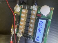
In the meantime, I did an experiment. I discharged the battery to about 23V (about 3.8V per cell). I installed the SMDJ33A diode and started the calibration. Unfortunately, one SLD8S28A diode has exploded... Can you tell me if I put everything together well? (Direction and place) Image is below.
I was tired then... maybe I did something wrong during calibration. I still wonder if I held the footswitch long enough... I dont remember offset number... When "Short!" come on LCD then I touched the electrodes and the TVS diode exploded... electrodes slightly melted
I must admit that I can replace burnt components, but I don't know much about electronics and how it all works

Thanks to you I know that the SMDJ33A diode works with too high voltage (maybe it caused the TVS explosion?). But what if the battery voltage is around 23V, will it work properly?
Thank you for help! I am grateful for your time
Compoundbike
100 W
I had some issues after adjusting min. Amp to 500 my K-Weld started to work again.
What's the stock parameter on this setting? 800?
What's the stock parameter on this setting? 800?
TrotterBob
100 W
I havent changed my default settings and yes it says 800 amps for minimum current.

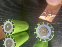
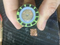
The SM8S26A looks like an OK replacement for the large SLD8S28A, but for a SMDJ28A it is overkill (but would of course work). Instead of SMDJ28A you can also use one of the other voltages starting from 24V.Sztef89 said:Hi! I am still struggling with the repair of the kWeld ... I am looking for a replacement diode. Will the one on the right (SM8S26A) be a good replacement for the original one SMDJ28A?
But as you keep killing the parts, something else must be horribly wrong. I suspect that either your battery is way too strong (i.e. has a too low internal resistance), or your wiring is bad. What is the total length of all current carrying leads added together? Did you configure the welder accordingly? Can I see a picture of your entire setup that shows battery and all leads? What exact battery model is that?
tatus1969 said:The SM8S26A looks like an OK replacement for the large SLD8S28A, but for a SMDJ28A it is overkill (but would of course work). Instead of SMDJ28A you can also use one of the other voltages starting from 24V.Sztef89 said:Hi! I am still struggling with the repair of the kWeld ... I am looking for a replacement diode. Will the one on the right (SM8S26A) be a good replacement for the original one SMDJ28A?
But as you keep killing the parts, something else must be horribly wrong. I suspect that either your battery is way too strong (i.e. has a too low internal resistance), or your wiring is bad. What is the total length of all current carrying leads added together? Did you configure the welder accordingly? Can I see a picture of your entire setup that shows battery and all leads? What exact battery model is that?
First of all I made a beginner's mistake... And the temptation of high power
New diodes SLD8S28A is waiting for second attempt to repair kWeld (I buy 4 pieces, just in case)
Now I waiting for SMDJ24A from Farnell (you recommend this because lack of SMDJ28A).On first attempt I replace only this small SMDJ28A -> SMDJ33A. Maybe it caused damage (diode voltage too high) or my mistake during calibration...
I'm still not sure if I solder everything well. Due to the burnout of paths, I changed the place of SMDJ28A. Can you confirm if I have kept good place and direction? Maybe I should put it as it was originally and connect the burned tracks?
Sztef89 said:
----------------------
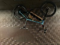
This is my (old) battery instalation, but I already disassembled it. The battery is definitely too strong ... I want to change to a 4S 4P LiFePo4 A123 2.5Ah (green) cells package. If it will be too weak, I will add more cells in parallel to get about 1400-1500A.
22.3V and 9.8mOhm... this is 2275A, and to high voltage for kWeld


tatus1969 said:Higher voltage means higher risk of arcing, and higher losses in the battery (by Ohm's Law, the battery ESR must rise to keep the current in the sweet spot of ~1500A).soylentgreen said:i noted there have been some users who have used 6S with and without success, and there was talk that high voltages doesn't play so well with copper?
This post help me understand what happen when we try to high voltage
spinningmagnets
100 TW
It is the amps that produce the heat. The kWeld was improved by popular demand so that it will work with a wider range of voltages, but...8V-16V is ideal, IMHO. Max out the amps, and add a cooling fan to the welder.
I'm about to order the Kcap and Ksupply. I'm having difficulty in selecting the correct power supply for the Kcap, can someone help me with the correct part number? Or confirm that this is the model I would need, https://www.amazon.de/-/en/379124-001-Supply-hstns-pr01-7001044-380622-001/dp/B00718YE24
I'm able to source this model in refurbished condition for like €60. Is that price fine? How much do new one's go for?
I'm able to source this model in refurbished condition for like €60. Is that price fine? How much do new one's go for?
Silvaticus
10 W
- Joined
- Jan 18, 2019
- Messages
- 66
The total length of the conductors is over three meters or 10 feet? Why do you need such long wires? Are you planning to use them as a heater?
After all, Frank recommends trying to bring the value closer to 1 meter.
You can connect your modules in parallel, although this will further aggravate your situation, since the resistance will drop and the current will almost double.
P.S. However, I did not pay attention to the fact that there are three modules and not two.
Nevertheless, if you disconnect one module, and connect the other two in parallel, then, according to Ohm's law, the battery is unlikely to give more than 2.3kA. You should also consider the significant drop on long wires. Therefore, most likely you will not exceed the current limit for kWeld. In any case, you can charge to a certain value, say up to 12.7 volts so that it does not exceed the threshold value.
spinningmagnets
100 TW
I don't know what bad things will happen with extra-long leads, but...they increase inductance. Please post what happens when you use it.
Silvaticus
10 W
- Joined
- Jan 18, 2019
- Messages
- 66
Not sure if this was addressed to me. However, long thin wires act as a current limiting resistor. Thereby increasing the overall resistance of the system. In addition, the overall efficiency is reduced. From personal experience, the most significant adjustment to the resistance of the entire system is made by wires. The current source is 0.4mΩ, the control board is 0.14mΩ, with a total resistance of 1.65mΩ.
The SMDJxxA must be placed at the left of the unit, close to where the original part was. Put the new large TVS at its original position, and add thick jumper wires from there to the rightmost MOSFET (left 5 legs). Make sure to leave out the short tab in the middle.Sztef89 said:I'm still not sure if I solder everything well. Due to the burnout of paths, I changed the place of SMDJ28A. Can you confirm if I have kept good place and direction? Maybe I should put it as it was originally and connect the burned tracks?
When seeing your battery leads, it is clear why the TVS diodes exploded. This has been inductive kickback, make sure to read and understand the section in the kWeld operating manual. It is also crucial to configure the welder correctly - for such long leads its max current is probably rather in the region of 1200 amperes only.Sztef89 said:This is my (old) battery instalation, but I already disassembled it. The battery is definitely too strong ... I want to change to a 4S 4P LiFePo4 A123 2.5Ah (green) cells package. If it will be too weak, I will add more cells in parallel to get about 1400-1500A.
Or put differently, as you were pushing more than 2000 amps through the system *and* have very long leads, the amount of stored magnetic energy becomes *very* large - probably in the order of a hammer drill punch or a cariac defibrillator shock.
They do, but they also represent an inductor. And that is what then kills the unit 8)Silvaticus said:long thin wires act as a current limiting resistor.
spinningmagnets
100 TW
Inductance will create a voltage spike in the circuit when the current is stopped.
I don't know the exact length of leads that begins presenting a problem, but...two leads of a half-meter each is perfect for low inductance.
To be able to reach the center of a large battery pack, I recommend making a shelf that is roughly 6-inches above the workbench, and this shelf can hold the kWeld unit and power supply.
This way, a large pack formed out of 18650 cells can be moved around with ease, underneath the welder, just a short distance away
Ran a few tests with my new-to-me kWelder hooked up to 2 6V 225Ah Lead Acid batteries in series with 1M total cable length.
Test materials on hand:
1. 0.2mm copper slotted H-strip
2. 0.2mm pure nickel slotted H-strip
3. 0.15mm nickel-plated steel slotted H-strip
4. 0.15mm nickel-plated steel strip
With the 0.2mm copper + 0.2mm pure nickel I got up to 95J, but the spot welds weren't as strong as I'd like at this level and I didn't want to push the welder any further. I had similar results with 0.2mm nickel + 0.15 nickel-plated copper without slots pushing up to the same power levels. At this higher output it seemed easier to accidentally blow through the material or only get a solid weld on one side of the slot with both combinations. Although, some of this could be user error, not pressing hard enough on the electrodes, and/or attempting to weld over previously pulled strips without sanding.
The combination of 0.2mm copper + 0.15mm nickel-plated steel went much better with consistently strong welds at only 70J.

To be fair, this wasn't really an exhaustive test of the material combinations, I just stopped testing when the copper+nickel-plated steel combo had good results.
I'm still holding off on my battery assembly since I'm wondering if I should electro-plate the copper strips with nickel beforehand. I see a lot of people have gone ahead without that corrosion protection on their copper conductors, was there ever a consensus in the community as to whether or not the nickel plating is necessary for long-term durability/reliability?
Test materials on hand:
1. 0.2mm copper slotted H-strip
2. 0.2mm pure nickel slotted H-strip
3. 0.15mm nickel-plated steel slotted H-strip
4. 0.15mm nickel-plated steel strip
With the 0.2mm copper + 0.2mm pure nickel I got up to 95J, but the spot welds weren't as strong as I'd like at this level and I didn't want to push the welder any further. I had similar results with 0.2mm nickel + 0.15 nickel-plated copper without slots pushing up to the same power levels. At this higher output it seemed easier to accidentally blow through the material or only get a solid weld on one side of the slot with both combinations. Although, some of this could be user error, not pressing hard enough on the electrodes, and/or attempting to weld over previously pulled strips without sanding.
The combination of 0.2mm copper + 0.15mm nickel-plated steel went much better with consistently strong welds at only 70J.
To be fair, this wasn't really an exhaustive test of the material combinations, I just stopped testing when the copper+nickel-plated steel combo had good results.
I'm still holding off on my battery assembly since I'm wondering if I should electro-plate the copper strips with nickel beforehand. I see a lot of people have gone ahead without that corrosion protection on their copper conductors, was there ever a consensus in the community as to whether or not the nickel plating is necessary for long-term durability/reliability?
Near an area with salt spray going to say yes
but a lacquer / epoxy whatever coating may be enough?
Personally I would like to investigate just tabbing the cells, and then using insulated fine-stranded tinned boat wiring.
So maybe getting the fast dis- / re- assembly advantage we would otherwise get from the solderless / no-weld methods so many have been working on.
Not relying on compression alone for solid conductive connections in such a high shock/vibration context.
Not in an area with salt spray, but I would like to take my bike on rides near the coast someday. That and I don't want to make a relatively permanent construction mistake upfront if corrosion has a chance of becoming a problem years later. Now that there are a lot of anecdotes of people welding bare copper, I wonder if there's been any issues?
On my last battery assembly (nickel strip connections only) I just wrapped each pack covering all of the exposed connections with the largest, fairly thick heatshrink Lunacycle sold at the time. This time around, I was planning on using Kapton tape over the connections and heat-shrinking again over top of that with some large clear heatshrink I got from Aliexpress. I just don't have any experience with copper corrosion and electrical resistance over time to say whether the wrapping above would help or if it's even necessary. It seems like electroplating nickel would be the safest route to go and it doesn't look like it's difficult to do, but still kind of a pain in the ass anyway. Maybe not a bad suggestion, but I don't really like the idea of epoxying the pack to cover the copper. Just my preference though.
As for mechanical stress and fatigue, I'm using the same arrangement I used last time, ABS plastic cell holders. These worked great for me before so with good spot welds, I shouldn't have any problems there.
Similar threads
- Replies
- 10
- Views
- 864
- Replies
- 8
- Views
- 3,393
- Replies
- 1
- Views
- 1,580