LaFree/Ford Think Ebike, lipo conversion

kfong

100 kW
Joined
Sep 2, 2008
Messages
1,957
Location
SE Michigan, USA
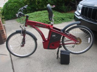
Addiction has set in yet again. I was looking for a bike to convert for a friend when I came across the Ford Think on Craigslist for $220. It’s a butt ugly bike but the price was what caught my eye. This would be cheap enough to convert or get working. Unfortunately the more I did research on it the less it would be ideal for my friend who was use to simple hub motors, I rarely saw her do any gear shifting.

What did catch my eye was the mention of a real torque sensor. Other things I liked was the big battery compartment and the fact that it was a mid drive setup. The downside after actually riding it was the poor ergonomics. The bike puts you too far forward from the pedals. Who designed the bike was definitely not planning to actually pedal the damn thing. It’s also quite heavy for a bike, even after taking the batteries off. The battery in the back forces the seat to be moved forward as well as the handle bars. Why they didn’t just extend the frame to compensate has left you with a poorly executed ebike design. I would need to get the seat farther back if I plan to keep it. It had enough features to peak my interest and now I own it :roll:

One of the reasons for the weird seat design is the way it flips up to remove the battery. View of battery compartment
 

Attachments

  • lf side view.jpg
    lf side view.jpg
    122.6 KB · Views: 1,862
  • lt side view seat up.jpg
    lt side view seat up.jpg
    123.9 KB · Views: 1,861
First thing to do is remove the ugly shell and see what's behind it.
panels removed.jpg

Here is the side lf side view without the panels
new left side view.jpg

Right side view
new rt side view.jpg

I like this new utilitarian look better. The kickstand must of come from some small motorcyle source. It's overbuilt and quite solid.
 
Here are veiws of the components, it came with a standard 7 speed cassette.
7 speed cassette.jpg

The left side has a speed sensor, interesting that it has more than one magnet. I assume this is to get a better feedback for the torque sensing algorithm.
speed sensor.jpg

Here is the dc motor, it has 2 plugs on the top side. It's a nice size so there is hope for it. I was thinking on putting a Turnigy 80-85 in it's place, that should really get it to move.
dc motor.jpg

Left side view of motor
left side of motor.jpg

Torque sensor?
View attachment 2

Motor Controller
controller.jpg

and the battery connector that I've read that is poorly designed.
Battery plug.jpg
 
Now onto the handle bar

Here is the display, funny that it has a shift indicator. No Ford Logo?
ebike display.jpg

Throttle, not sure what the econ mode does
throttle control.jpg

Shifter
gear shift.jpg

lock of some sort that I haven't a clue what it would be used for? It and the RST elastomer fork will need to be tossed.
 
That's all for now, tomorrow I will take apart the battery and find out why there are 3 terminals. Hopefully I will be able to get the bike powered up and running. I plan to overvolt current setup. I've read the controller should handle 36 volts, and the third terminal is for power to the controller, if this is the case I can use a DC-DC converter to run it.
 
Looks like the motor driver is bad, when powered up I get a constant flashing of the LED on the empty indicator. There is a diagnostics mode you can access by using a push pin onto the back of the display. This follows the Lafree manual
https://docs.google.com/viewer?a=v&pid=sites&srcid=ZGVmYXVsdGRvbWFpbnxmb3JkdGhpbmtiaWtlfGd4OmRmY2IxODk1NGI2ZDU5ZA
But all it really indicated to me was all sensors were functional, no info on what the blinking led indicated. The controller in the battery box is more than just a battery monitor. I see current measurement as well as other functions being monitored by a PIC processor. There is an on board regulator in the battery controller, so no need for a DC-DC if you stay within the regulators specs. I was able to see 5 volts from the regulator, but was not able to decern what the center pin of the battery connections does. I can hear a relay switch when powered. This relay must be located in the motor controller. To verify the motor works, I connected a 12v battery directly to the motor terminals with the controller removed. The drive train sounds quieter than the cyclone setup. I suspect the motor controller is bad, probably the Fets overheated. I will take this apart next, unfortunately they did not put in plugs to remove it from the bike easily.

The seat position is too far forward. I will need to move it back an inch if I plan to use it. Adding a Nuvinci hub is another likely addition.
 
That is a neat bike, Kin and should go pretty well. I too have recent interest in Torque sensors as I will be attempting to install a Pedelec system on my trike. This one uses a "Torque Emulator" in a new Sinewave controller from (wait for it)...........BMS battery. I have never dealt with them before, but we shall see how it goes. If this system does not work out I guess I am "in for dime infor a dollar" and will go with Grins Thun sensor or start with a CycleAnalyst and the ring like Telektik did. All at much greater cost, unfortunately. Oh yeah I have not tested the SmartSwitch yet as the trike has been down. Will be running next week again.
otherDoc
 
David, if it wasn't for the torque sensor. I would of not found the bike to be much of much interest. I already have too many Ebikes. The mid drive motor is well designed, so that is a pleasant find. I was looking into a Thun torque sensor for my trail bike but have decided against it, from reading this thread, and the main fact it is not Isis. http://endless-sphere.com/forums/viewtopic.php?f=6&t=36959&start=150. Have you looked into just having the CA do a simulated torque. The latest version has this feature, Telektik describes it in the link. It does not sound good for trail riding, but seems great for commuting.

Looks like they potted the motor driver. This puts off the possibility of repairing it. The potting compound is similar to epoxy. I would be better off replacing it with a generic controller at this point, would of been fixable. Maybe I'll try to mill part of it off, just so I can get to the FETS.

I found out the lock in the front is actually a wheel lock, pull it out and slip it across the spokes to prevent the bike from moving. Unique enough to be useful, since I usually just lock the tires most of the time if I'm in a hurry.
 
The latest version has this feature, Telektik describes it in the link. It does not sound good for trail riding, but seems great for commuting.

Yes I just read it and it may be the deciding factor in my getting a Cycleanalyst.
Thanks Kin
otherDoc
 
I took apart the display which has a pic micro. The center pin of the battery plug labeled C is actually a communications line. It gets messages from the display as well as the motor controller which is probably PIC based. You can see a serial data pulse train on the oscilloscope. There is a fault detected on the bike, but it's not clear what it is. Brake switches work, torque sensor works, contacts are clean, test diagnostics seem fine. You can hear the relay click in but the motor controller immediately shuts down. The focus is back onto the potted motor controller, just needed to be sure no external faults exists now that I'm aware of the communications between modules.
 
I've decided that the motor controller isn't serviceable with the epoxy potting compound used to seal it. I took a look at the battery box and the PIC16c711 used for control. The data sheet shows it as a 1k memory micro with (4) 8 bit a/d channels
http://ww1.microchip.com/downloads/en/DeviceDoc/30272a.pdf
I will see if I can reprogram this chip or swap it out. The reason this would be useful is because the board has a current shunt. This would make a simple battery wattmeter. I can use the same serial communications line as well. The board is setup with a master fuse and a transistor output. The charge port can be reused as a 7S balance port, but I will probably use my DB balance board so I can run 12 or 14S setup. I can use my smart switch board as well to power up the system. The battery box can be reused for all of this.

I could reuse even the display and repurpose it. It has 5 LEDs, but I'll probably trash it and use an LCD display. The motor controllers only value are the connectors. For now I will stick with the brushed setup until the motor fries. Replacing it with an RC motor might be a bit of a challenge. Won't know until the motor is apart, but I might as well run it till I get to that stage.

This project was completed and sold, I lost interest in the bike once I realized how crappy the ergonomics were. They never designed it to be actually pedaled, the weight was also a factor. It does make a good cheap utility ebike.
 
Back
Top