large road legal electric go kart build. need help!
- Thread starter falshami
- Start date
Ah ok, that is a 2KWH pack (12s3p). I have 3 of these 2kwh packs plus 1 x 1kwh pack (6s3p) to give me 7kwh (42s3p) and 144v nominal. I could probably charge them to around 175v or so but I generally only take them to 170v.
So for your pack that does mean a limit of 50v. Sorry for the bad news. I am sure you will work it out though.
So for your pack that does mean a limit of 50v. Sorry for the bad news. I am sure you will work it out though.
This is what I have:
http://hybridautocenter.com/HAC4/index.php?option=com_hikashop&ctrl=product&task=show&cid=96&name=7kwh-lithium-battery-pack-chevrolet-volt-155v-45ah-42-cells&Itemid=605
and it lasts me about 20 minutes in my 500kg car....but that is mostly full throttle and loads of violent acceleration and deceleration.
yep that is what i have, im running mine at 44-48v im upping the amp hours since i have no doubt that at roughly 350kgs i should be able to get a 40 minute run time, or maybe an hour afterall im running at about 100AH, and looking into upping it to 150AH possibly 200AH if the funds appear, im also looking into cooling the battery pack via its cooling passages. It looks like im probably going to use a 54.6v charger with a BMS system to cut off at 50.4 this might be my best bet for now and future use
another question is this, if i were to add one of these charging ports to my vehicle, does it mean i could simply use blink chargers wherever i went? because if i understand correctly. the BLINK chargers output 240v. which means if i connect my soon to be coming charger. set it to 240v, and let that be what is connected to that port, i should be able to charge at any electric car recharge station? does this sound right?
http://www.ebay.com/itm/2013-CHEVY-VOLT-1-4L-BATTERY-CHARGER-CONNECTOR-RECEPTACLE-22822889-OEM-66355-/381907231856?fits=Make%3AChevrolet%7CModel%3AVolt&hash=item58eb71e470:g:~OAAAOSwA3dYTFK5&vxp=mtr
http://www.ebay.com/itm/2013-CHEVY-VOLT-1-4L-BATTERY-CHARGER-CONNECTOR-RECEPTACLE-22822889-OEM-66355-/381907231856?fits=Make%3AChevrolet%7CModel%3AVolt&hash=item58eb71e470:g:~OAAAOSwA3dYTFK5&vxp=mtr
I am still new to real chargers. So far I have only used a hobby charger over multiple weeks.
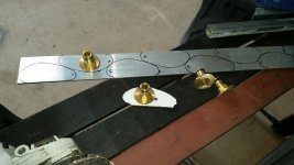
I made some dodgy connectors for the cooling ducts. I sandwiched some garden hose fittings between two pieces of aluminum and glued it together with silicon. The aluminum is shaped to match the odd shape of the openning and I have holes drilled at each end to accomodate the bolts that hold the whole module together.
I made some dodgy connectors for the cooling ducts. I sandwiched some garden hose fittings between two pieces of aluminum and glued it together with silicon. The aluminum is shaped to match the odd shape of the openning and I have holes drilled at each end to accomodate the bolts that hold the whole module together.
so update for the day, still working on finding a BMS system and dealing with my new found info that my batteries are 44v nominal and not 48v. however i did manage to go ahead and pick up some new rims and have started painting parts of my chassis while i wait for my parts to come in!
http://www.visionwheel.com/wheel/1083/506/
these are the rims, i got them in 14x8 and am looking at some tires for them , im thinking some 215/70R14 sized tires will lift the buggy up a little make it look a bit meaner as well!the new tires will be much smoother than the knobby tires so rolling resistance should go down significantly however being larger wheels there is a bit of a weight increase im sure, but the rims are aluminum, and the tires should be less meaty than the stock ones so im hoping it evens itself out, they are also less wide in the back so maybe that will help since the driven wheels are the rear and less rotational mass is good!

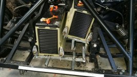
This is part way through the construction

This is with the adaptors in place ready to take the cooling hoses.
I cut pieces of aluminum to match the duct opennings (2 for each openning).
I drilled holes to accomodate the garden hose fittings.
I drilled two smaller holes to accomodate the long bolts that hold the battery modules together.
I cut the connector part off the hose fitting leaving a nice flat washer shaped area with the nipple protruding.
I placed the nipple through one of the aluminum plate with silicon to seal it.
I placed the second plate on the other side of the washer shaped part of the nozzle with more silicon to seal it.
I allowed to set (with some bolts holding the holes in alignment.
Then I bolted them in place with more silicon to seal them against the battery modules.
I have had very few problems in the way of leaks. They have been in place almost 12 months and I've only needed to top them up once. The only leaks I have had have been in the hoses between the batteries and pump.

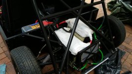
You can see the radiator in this pic. It is the heat exchanger from under the dash of a local GM car (Commodore). But I think you could use the equivalent from any modern car. Just choose one that fits your space.
No regulator, just a manual switch. But so far I have not been getting significant heat. But I am still gradually ramping up the power so it will likely become more and more important.
I would be happy to make some up. But don't forget I am in Australia so delivery time might be an issue.
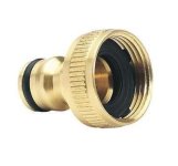
The hose fittings are quite common here. I just opted for the brass ones for strength. The bit I removed was the bit that generally screwed onto a garden tap. and there was a rubber washer in there which I also removed.
Here is a link to a similar one.
http://www.ebay.com.au/itm/like/291792173583?lpid=107&chn=ps
oh and one more note. I also made some steel brackets that used both bolts to secure the batteries down. These are in a sort of an "?" shape so the middle part of the braket was clear of the hose fitting. I opted to make this bracket seperately from the coolant adaptor incase I want to remove the brackets I don't necessarily need to break the silicon seal.
okso you used a regular hose mal end and cut off the screw bit . this makes alot more sense how many amps are you drawing from the batteries now without having to usee too much cooling?im going to use the radiator from the go kart that it came with, im realizing its a good part after all so i might as well use it! your setup looks incredible! yes, lets throw you on a plane and get you down here to help me build! haha i think i may need those adapter plates more than anything else that you made. i guess i may have to learn how to make them. and with that little leakage i am quite impressed at your handy work!
im actually considering using a smaller radiator and attaching a peltier unit to it with a temeperature controller so that it would just keep the battery either cold or warmer depending on what it needed, it shouldnt be hard with these items
http://www.ebay.com/itm/122232531948?_trksid=p2060353.m2749.l2649&ssPageName=STRK%3AMEBIDX%3AIT
http://www.ebay.com/itm/142158678643?_trksid=p2060353.m2749.l2649&ssPageName=STRK%3AMEBIDX%3AIT
http://www.ebay.com/itm/302021329702?_trksid=p2060353.m2749.l2649&ssPageName=STRK%3AMEBIDX%3AIT
thoughts?
http://www.ebay.com/itm/122232531948?_trksid=p2060353.m2749.l2649&ssPageName=STRK%3AMEBIDX%3AIT
http://www.ebay.com/itm/142158678643?_trksid=p2060353.m2749.l2649&ssPageName=STRK%3AMEBIDX%3AIT
http://www.ebay.com/itm/302021329702?_trksid=p2060353.m2749.l2649&ssPageName=STRK%3AMEBIDX%3AIT
thoughts?
The adapters are quite simple to make so long as you have a drill and a grinder.
So far I have only ever drawn 350amps for all of about a second. I think that will rise a little as I turn the controller up. But I have capped the battery amps at 500amps and I won't be increasing that.
So far I have only ever drawn 350amps for all of about a second. I think that will rise a little as I turn the controller up. But I have capped the battery amps at 500amps and I won't be increasing that.
how do you cap the battery? my controller wont push past 320 amps right now i think, either that or 412, ill have to go look, although i dont really want to push past 300 amps . i jsut want to be able to cruise at 45mph and pass at 60 if i need to 
I have only used my new controller once in anger. It is a Zeva 1000amp unit. I purchased it with the Management system which includes a touch screen. The Management system allows all sorts of limits (I'll paste them below). One of the settings is the maximum battery amps. My old Curtis controller didn't have anything like that.
How do you know how much current you are drawing?
How do you know if it is battery amps or motor amps?
I assume you know that controllers can reduce volts in favour of amps at the motor?
I doubt you will be able to get up to 60 without a little more than 320 amps. My old controller was only capable of getting me to about 50mph at 350 battery amps.
I can't really say too much more until I know how you are measuring those amps.
My wife is from Luisianna and has been tring to talk me into a Christmas trip to the US for some time. So I think a big US trip is on the cards for me. I will have to include Arizona on the agenda.....Assuming Trump doesn't close the borders to us EV enthusiasts because we beleive there is truth to climate change.  I better start work on a new EV capable of leaping over walls.
if you need help building a bouncing EV car im in, im sure we can use electro magnetic shocks to get you over the wall! haha yes come down id love to chat in person! are you in australia? if so im dying to visit! what controller is that? and touchs creen? i want more info on these electronics, what weight was your vehicle when trying to achieve these speeds? im trying to figure out the amount of torque my motor will output at 15kw... the math is wonky at best for it
Yup, I am in Australia, Queensland to be precise. Happy to give you some tips on things to do and see when you get here. Now is a good time to visit as the exchange rate is in your favour.
I opted for Zeva electronics to replace my old (blown) system as I liked the idea of local (Australian) support. So far I have been very happy with the product and the support. Here is their web site:
http://www.zeva.com.au/
I purchased:
1x EVMS Core
1x EVMS Monitor
4x 12BMS modules
1X MC1000C controller
Feb 12 is my next event so I am really looking forward to giving this system a more thorough test. Up and down my driveway just doesn't prove anything.
The car was about 530KG when I achieved those speeds. 650KG with driver. But again that was with the old controller which was not up to the task plus gave very little in the way of information about what was happenning. All I know is the launch was excellent, 2nd gear was acceptable but 3rd or 4th were terrible. Hardly any accelleration at all past 45mph. There are really only 3 components that could limit performance: motor, controller and batteries. The ADC 9inch is a stonking big motor that is capable of driving a 1000KG car quite well so unless there is an unseen issue with it I can pretty much discount that as the limiting factor. The batteries have never produced any noticable heat, so that means they are not being stressed. So that leaves me with the old controller as being my limiting factor. Not to mention it eventually went bang.
You can see all my videos including test runs by searching Youtube for Full Charge Motorsport. The khanacross runs are the ones which demonstrate the top speed limit. Plus there was another video when I was specifically testing top speed on the drag strip. Keep in mind the speeds are all in KMPH.
As a side note: At the first event using the new controller I didn't realise it was resetting back to the defaults between runs (due to the way I wired it). So the default settings were limiting the motor amps to 500. But I was still getting better performance than the previous controller. So this time around I am expecting to set the limit at around 800amp (to start with). I should see significant performance improvements.
There are various graphs showing torque output of the various motors. Try tracking one down. I don't think torque will be an issue for you. More likely the limiting factor will be the power required to overcome the aerodynamic drag that increases with speed. This is also playing a part in my car as mine is effectively shaped like a brick.
you spent a heck of a pretty "penny" on your setup, im buying a bms with i think a screen for 250, im buying a standard 48v charger and adding a relay to automatically shut it off at 50 volts. do you have any idea what amount of torque my motor may put out? i will be running it at 15kw peak so roughly 20hp, so if i need the power it is there, and at only 8-9 hundred pounds i should be able to get it scooting. i ran a few calculators to see what it takes to run my vehicle at 60 mph and supposedly at my weight and drag coefficient im only looking at 10hp, which means with the amount of power i have i should be ok, my only concern is that my power to weight ratio is really poor, but i dont know how that goes for electric vehicles, roughly 40 pounds per hp is what my vehicle will have, which to put into perspective, my Chrysler crossfire at 3200lbs and 230 hp has a power to weight ratio of 13:1 and an acceleration to 60 time of 6.5 seconds, with a drag coefficient of around .37 so im lost as to what this vehicle will do, i dont even have the slightest clue how it will perform, will it shred my gear box? or will it struggle to move? im up in the air. and if what is said is true that demanding 300 amps from those volt batteries isnt a big deal then that also puts me at ease a bit, im using a torque converter to allow the motor to draw fewer amps on take off and add gear ratios continuously to make a top speed easier to reach . what are your thoughts? we have made alot of progress on this build once the motor comes in and torque converter we can start installing!!!
Similar threads
- Replies
- 9
- Views
- 1,981
- Replies
- 1
- Views
- 616
- Replies
- 12
- Views
- 585
- Replies
- 2
- Views
- 932
- Replies
- 11
- Views
- 667


