• Howdy! we're looking for donations to finish custom knowledgebase software for this forum. Please see our Funding drive thread

Lebowski's motor controller IC, schematic & setup, new v2.A1

The hall sensor information from Arlo explains to me why there's trouble sampling the back-emf.

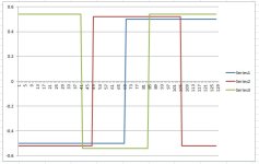
This is a plot from Arlo's hall data:
Arlo_halls.jpg

If you look at the graph you can see the hall spacing is really irregular and especially
series3 has a weird very high dutycycle (65%). The main killer for the sampling however is the
spacing between the series2 and series3 around position 45. The chip expects somewhat
evenly spaced halls (which would be a transition every 21 positions). It can deal with tolerances
on this but a spacing between transitions of only 7 positions is really out of proportions. What happens
is that the time between two hall transitions is extrapolated (using the known hall positions)
to the time for a full e-period. If this then differs more than 12% from the running average e-period
time it declares lock is lost and stops the back-emf sampling (basically it samples the voltages but
then has no clue anymore where in the e-period the samples were taken). With a very small
space between transitions the time between the halls is multiplied by a huge amount, easely
tripping the 12% max. error allowed.

Just to compare, this is the plot from the data posted by Nieles:


I actually have the feeling one of Arlo's halls is broken (hall 3), it would be interesting to spin
the motor with a drill (constant rpm) and to look at the output signal of hall 3. I think it will not
be a nice regular square wave. My reasoning: during the calibration the average falling edge was on position 41,
the back-emf sampling stops because of an unexpected hall transition at position 18 for the first
measurement posted and 12 for the second measurement posted by Arlo 2-3 posts ago.
 
The back emf posted by Nieles looks good, this is the raw sampled data:
View attachment 1
and this then the reconstructed:
Nieles_reconstructed.jpg
You actually discovered a feature :mrgreen: Generating the reconstructed data is actually
a 2 step process. First it reconstructs the waveforms to within a +1 / -1 range. Then it
has a quick look at the setup pin to see whether it's in motor or setup mode. In setup mode
it leaves the data as-is, in motor mode it scales it with a PWM frequency related value.
The PWM scaled data tells me it was generated with the setup pin in motor mode, this has
however no consequences for the stored waveform data.

Looking at the video of the sensored trials, I'm assuming there's no led in the video for drive_0 ?
Looking closely I can see that the controller does also go into drive_3 but exits it almost immediately.
Based on this the things I would change in the setup:

Code:
a) loop sample frequency: 38.01 kHz
b) 1st order phase loop integrator coefficient: 53.0000
c) 2nd order phase loop integrator coefficient: 0.3099
d) amplitude loop integrator coefficient: 1.5000
e) maximum amplitude: 200 %
z) return to main menu
I would recalculate the values of b, c and d according to the setup manual. As it's a hubmotor, I would use
y=256. For unknown motor LR_delay, I would take 2 milliseconds as a slow guess. Then, with f_sample = 38 kHz and
f_pwm = 20 kHz:
option b -> 3.37
option c -> 0.005
option d -> 0.57
If it works you can reduce LR_delay. If it does not I would recalculate with y=1024.

Code:
a) sensored or sensorless: SENSORED
b} sensorless startup: PUSH START
c} e-rpm limit sensorless self start: 1183
d} e-rpm reached before transition: 47 %
e} minimum current push start: 2.9 A
f} push start current, error allowed: 24 %
g] erpm sensored to sensorless transition: 500
h] transition time sensored to sensorless: 99 milli-sec 
i) return to motor start below 500 erpm
j) controlled slowdown for direction change: YES
k) phase current for controlled slowdown: 0.9 A 
l) motor maximum, forward: 99.97 k-erpm 
m) motor maximum, reverse: 39.99 k-erpm 
n) motor standstill voltage threshold: 0.49 V
z) return to main menu

Here, it's better to have some hysteresis between options g and i. Try 300 for option i.
The time specified with option h is extremely short, I would recommend to start with
1000 to 2000 msec and work your way down.

By the way, as the motor was running OK in sensorless mode I think the issue is in the
running modes menu and not so much in the control loop menu.
 
nieles said:
so it is normal the reconstructed data is not scaled beteween 1 and -1?

If you generate the reconstructed data with the setup mode pin connected to ground the
reconstructed data will be in the +1 / -1 range. With the setup mode pin to vdd it will
be as you posted it, post-scaled with a PWM related parameter. You can try it, keep the
setup pin connected to ground and the reconstructed data will be between +1 / -1.

I'm guessing you have a push-button switch to ground which you press will giving it a
reset to bring it in setup mode. Because you released the push-button during data
reconstruction it post-scales it with PWM data. I had a toggle switch connected to my
setup pin, not a push button :D

I'm making a list of things to change, this is now on the list :D
 
when i was programming the controller yesterday i noticed something odd.
when in setup mode and want to return to motor mode, you give the controller a reset. but when i do this, sometimes it will not respond to the "enter press" when returning to setup mode again. when this would happen i have to restart termite and cycle the connection to the rs232 adapter. The only way this would not happen is when i press the reset (to return to motor mode) when i am in the Main menu. so ALWAYS first return to the Main menu before resetting the controller (this could be part of arlo1's reset problems?)

this was in Termite (2.8) on WinXP
i havnt tested the same scenario on Ubuntu.
 
I've never seen this (but then again, I've always used gtkterm under Ubuntu). I always resetted it
straight after saving the data in the EEPROM menu, I never first went back to the main menu.
From the chips point of view I don't see how this would work.
There can be some glitches on the RS232 pins of the chip on power up, this would be interpreted
by the RS232 as meaningless (non-ascii) characters which maybe upsets Windows ? But why this would
be different when resetting from the main menu, no clue. :?:
 
Lebowski said:
The hall sensor information from Arlo explains to me why there's trouble sampling the back-emf.

This is a plot from Arlo's hall data:
View attachment 1

If you look at the graph you can see the hall spacing is really irregular and especially
series3 has a weird very high dutycycle (65%). The main killer for the sampling however is the
spacing between the series2 and series3 around position 45. The chip expects somewhat
evenly spaced halls (which would be a transition every 21 positions). It can deal with tolerances
on this but a spacing between transitions of only 7 positions is really out of proportions. What happens
is that the time between two hall transitions is extrapolated (using the known hall positions)
to the time for a full e-period. If this then differs more than 12% from the running average e-period
time it declares lock is lost and stops the back-emf sampling (basically it samples the voltages but
then has no clue anymore where in the e-period the samples were taken). With a very small
space between transitions the time between the halls is multiplied by a huge amount, easely
tripping the 12% max. error allowed.

Just to compare, this is the plot from the data posted by Nieles:


I actually have the feeling one of Arlo's halls is broken (hall 3), it would be interesting to spin
the motor with a drill (constant rpm) and to look at the output signal of hall 3. I think it will not
be a nice regular square wave. My reasoning: during the calibration the average falling edge was on position 41,
the back-emf sampling stops because of an unexpected hall transition at position 18 for the first
measurement posted and 12 for the second measurement posted by Arlo 2-3 posts ago.
I just slid the halls into place and have not glued them permanently so I just had a look and one is on an angle so it might cause this. I will try to line them up better and glue them.
 
did some more testing today, but i cant get the motor to spin with a load to to motor.
i am in push start brushless mode, and when i spin the motor and try to put a light load to the motor(with my hand) it cuts out (to drive 0 )
i think i am tripping either the menu d, option f or menu d, option g.

settings tested
menu d:
c: 40 A
d: 15 A
f: 5 A
g: 5 A

Menu d:
c:100 A
d: 15 A
f:10 A
g:10 A
 
There's a good chance the problem is in the control loop menu, options b,c and d (the values for
which the computations are given in the setup manual). Having these values too large will make the
controller effectively jump all over the place (as the updates are too big).
You right in thinking you're tripping menu d, options f & g (the error current settings, error current trip
level is calculated as option f + amplitude * option g, with amplitude in the 0..2 range). This can be
caused by the controller jumping all over the place due to too large control loop settings...

Did you try the suggested values I PM-ed you ? Can you PM me the contents of the menus ? Hub motor or RC ?
 
not sure what settings you PMed me.

i am testing with my RC motor.

settings:
menu E:
b: 13.5 ( 3*1024/228 )
c: 0.02 ( 1024/(228^2) )
d: 0.6 ( 20000/458*0.002*38000 )
e:100%

x: 3*0.002*38000=228
y: 1024

what would be a good initial guess for the d and e parameters?
could there be a typo in the manual? on slide 15, it states options b, c and d are explaned on the next slides. but on slide 18 it explains the setttings for e instead of d.

if i am correct in thinking slide 18 is for setting d, what should i use for the setting e? i used different values and i get higher rpms with a higher value for e.
 
nieles said:
not sure what settings you PMed me.

i am testing with my RC motor.

settings:
menu E:
b: 13.5 ( 3*1024/228 )
c: 0.02 ( 1024/(228^2) )
d: 0.6 ( 20000/458*0.002*38000 )
e:100%

x: 3*0.002*38000=228
y: 1024

what would be a good initial guess for the d and e parameters?
could there be a typo in the manual? on slide 15, it states options b, c and d are explaned on the next slides. but on slide 18 it explains the setttings for e instead of d.

if i am correct in thinking slide 18 is for setting d, what should i use for the setting e? i used different values and i get higher rpms with a higher value for e.

Thank you for this post, I hadn't seen yet that. You're right, slide 18 is for option d. :oops:

Option e is the amplitude of the sine waves, 100% is a sine wave which exactly fits in the supply without
distorting or clipping the waveform. Above 100% the tops of the sinewaves are flattened as they run into
the limit of the supply.
Upto 100% with the sinewaves the motor runs quietly, once the clipping of the sinewaves
starts (over 100%) the motor gets more noisy.
Because the clipped waveforms represent a higher effective voltage the motor will speed up
to higher rpm when you go over 100%. Also the max power output will increase by about 20% (with 200%
as max amplitude versus 100%). But, at the penalty of more noise.

When your motor runs correctly with the values you calculated here I recommend you to
reduce the LR_delay from 2 downto 1 milli-sec or even 0.5 milli-sec and recalculate the
parameters. The control loop will respond more quickly when you use a lower LR_delay
value, but if you use too low a LR_delay value the control loop becomes unstable. When unstable
the controller will be jumping out of drive_3 very easely, at this point increase LR_delay
again. Also when unstable the controller can get stuck in drive_3 with the motor making a
funny noise.

Did you manage to load the hubmotor, you mentioned it left drive_3 when you braked the wheel
with your hand ? How did you test this ? Keep in mind that the throttle is torque based, if
you adjust the throttle such that the motor turns a certain rpm the torque is just right to overcome
the friction of the system at that rpm. If you put your hand to it it will immediately slow down
the wheel. The controller will not give extra throttle automatically to try to keep the speed
constant ! As you brake the hub you must increase torque (more throttle) to keep the speed up.

You also showed in the youtube clip that in sensored mode with the hubmotor the controller
did not go into drive_3, how is that now ? I PM-ed you some setting in reponse to this issue.

Also, I remember seeing that you use 4 for the IIR filter (option h, menu d). Have you tried increasing
this to 6, 7 or 8 ? A higher number prevents more effectively prevents the controller from leaving
drive_3 when a glitch occurs in the error current. Going too high though (11 or higher) can prevent
the controller from detecting a serious error condition (like loss of control).
 
Just found out, the options sensorless selfstart and combfilter ON do not go
well together. The combfilter removes the little bit of noise from the system
that the sensorless selfstart needs to start the motor.... Will update the
manual accordingly.
 
got my controller up and running!! i went outside for a quick test run, and man this controller is awsome. 100% smooth throttle response, and almost no noise from the motor. with other controllers there was always noise from the motor, but now it is almost silent. i couldnt make a vid unfortunately, because it was already dark outside.

some pictures from the test setup:

it is one big mess of wires lol..
IMG_20120306_195853 (1).jpg
IMG_20120306_195807 (1).jpg
IMG_20120306_195841 (1).jpg

i used a ubec (http://www.hobbyking.com/hobbyking/store/__10313__Turnigy_5A_8_40v_SBEC_for_Lipo_.html) for the 5v
and a diy supply based on the re LM5008 for the 12v (20-95v in, 12v 0.3A out)

motor: aeolian 6374 Kv:200
battery: 5S 10AH
controller setup:
Sensorless, Pushstart
Phase current: 40A
Battery current: 15A
Code:
########################################
#   (c)opyright 2012, B.M. Putter      #
#   Adliswil, Switzerland              #
#   bmp72@hotmail.com                  #
#                                      #
#  experimental, use at your own risk  #
########################################


a] calibrate hall sensors
b] determine coil positions
c) PWM parameters
d) current settings
e) control loop parameters
f) throttle setup
g) running modes
h) CAN bus setup
z) store parameters in EEPROM for motor use

------> a 

a] number of e-rotations: 30
b] calibrate hall positions
c] table out hall signals
z] return to main menu


------> b 

a] number of back-emf samples: 850
b] calibrate coil positions
c] reconstruct waveforms based on extracted parameters
d] table out data arrays
z] return to main menu


------> c 

a) PWM frequency: 20kHz
b) deadtime: 599ns
c) dutycycle testsignal: 50%
d) toggle high side polarity, now active HIGH
e) toggle low side polarity, now active HIGH
f) test PWM signals
z) return to main menu


------> d 

a) number of current sensors: 2
b) current sensor transimpedance: 10.00 mV/A
c) maximum motor phase current: 29.9 A
d) maximum battery current, motor use: 14.9 A
e) maximum battery current, regen: 0.0 A
f) maximum shutdown error current, fixed: 4.9 A
g) maximum shutdown error current, proportional: 4.9 A
h) IIR filter coefficient: 6
i) use additional comb filter: YES
z) return to main menu


------> e 

a) loop sample frequency: 39.00 kHz
b) 1st order phase loop integrator coefficient: 17.5499
c) 2nd order phase loop integrator coefficient: 0.0333
d) amplitude loop integrator coefficient: 0.7459
e) maximum amplitude: 100 %
z) return to main menu


------> f 

a) calibrate throttle 1
b) calibrate throttle 2
c) polynomal coefficients throttle 1 (x, x^2, x^3): 1.0000, 0.0000, 0.0000
d) polynomal coefficients throttle 2 (x, x^2, x^3): -0.0002, -0.0002, -0.0002
e) use analog throttle 1: YES
f) use analog throttle 2: NO
   receive throttle over CAN: NO
g) TX throttle over CAN: NO
h) test throttle
z) return to main menu


------> g 

a) sensored or sensorless: SENSORLESS
b} sensorless startup: PUSH START
c} e-rpm limit sensorless self start: 1000
d} e-rpm reached before transition: 78 %
e} minimum current push start: 3.4 A
f} push start current, error allowed: 21 %
g] erpm sensored to sensorless transition: 500
h] transition time sensored to sensorless: 99 milli-sec 
i) return to motor start below 500 erpm
j) controlled slowdown for direction change: YES
k) phase current for controlled slowdown: 0.9 A 
l) motor maximum, forward: 102.57 k-erpm 
m) motor maximum, reverse: 41.03 k-erpm 
n) motor standstill voltage threshold: 0.49 V
z) return to main menu

------> h 

a) CAN 'address': 1990
b) CAN CFG1 as per Microchip 30F manual: 64
c) CAN CFG2 as per Microchip 30F manual: 664
   RS232 output rate: 3901 Hz
z) return to main menu

------> z
Next up:
etch a PCB for the controller chip, to clean up the big wire mess.
some more testing with higher current settings!
 
This gets me so excited!!! Cant wait to do more testing just need some more bread board if its not here by this weekend i will get some at the source because i have a 4 day weekend!
 
Awesome! I love the breadboard. Don't hit any big bumps. :wink:

I guess one of the next steps is to lay out a circuit board that holds all the parts other than the power stage.
 
fechter said:
Awesome! I love the breadboard. Don't hit any big bumps.

I guess one of the next steps is to lay out a circuit board that holds all the parts other than the power stage.

yes that is the plan, working on the layout now


did some more testing in sensored mode.

the motor locking up like i showed in the last post still happens, but after some tries and turning the motor by hand i can get it to run.
whitch tells me it is probably has to do with the calibration of the current sensors. this motor has a no-load current of around 1-2A so that is part of the problem. i will get some acs714 sensors in my next mouser order to do some more testing on this.

in the vid below you can see the motor locking up in the beginning, then i got it running. the noise is coming from the frame the motor clamped in, the motor itself is really quiet. the second part of the vid shows some abnormality of the controller. after i release the throttle it almost fully spinns down, but then applies some throttle again. could be some noise on the throttle line, because i dont have the filter in place. (i did program the throttle with a small dead zone)
just remembered something, could this have something to do with the controlled slowdown?
vid:
[youtube]6C7sMk23cG0[/youtube]


i also did some tests with my outrunner RC motor. to get the push start working. so as you suggested i turned off the combfilter. that really didnt do anything noticeble. when i apply throttle, the motor turns 3-5 degrees to line up with a pole on the stator an then just stays there. it is really hard to turn the motor by hand when throttle is applied. an other thing that sometimes happens, it turns for a quarter turn, and then goes to drive 0.
 
I think it is indeed the noise in the throttle line, calibrate it with a bit larger deadzone. The controller IC
has the option to give internal variables out during motor use (page 27 of the setup manual), looking at the
noise on throttle 1 is plain scary (if you don't use an RC filter). The active slow-down you mention is only
used when you apply reverse, not when you close the throttle.

In the second part of the video, it this the sensorless selfstart ? It seems to be starting on its own... Or is this
hall sensored ?

I played around with hall sensored myself yesterday evening and think I found out what's going on. There's
an amazing amount of noise on the hall sensor outputs once the PWM of the output stage is activated.
I always thought my particular hall sensors were the problem, I have analog hall sensors which give a
kind of 'digital' output (they saturate because of the high magnetic field), so I thought proper digital
hall sensors would not have the noise I'm seeing. But judging from your difficulties, digital hall sensors
also suffer from this... What I use is a 2200 Ohm / 100 nF RC filter inbetween the hall sensors (+2200 ohm
pull up resistor for open collector) and the hall sensor input pins of the controller IC. Can you try this ? I would re-calibrate
both the halls and coils (main menu options a and b) after this. Again, looking at the internal variable
for the e-phase, phi, it's clear there's a lot of noise on this when there's no RC filters in the hall lines.
What I noticed is that without the hall sensors the motor feels weak in drive_1 (hall based startup),
can sometimes even go in reverse and basically sounds not health. I'll update the schematic...

The delay caused by the RC filter in the hall signals is not important as the controller transides to sensorless
at a few 100 to 1000 e-rpm.

About the current sensor offset, this will be seen as a large error current by the algorithm.... It calibrates this
away but only in drive 3. To stop it from conking out you need an appropriate value for menu d, option f (fixed
part of error current allowed). But in your case I think it's the noisy hall signals messing up.
In sensored, in drive_1 the motor runs on the hall sensor information only. After sufficiently high e-rpm is reached
it shifts into drive_2. In drive_2, over a certain amount of time, the sensorless control loop is gradually dialed in.
Then it switches to drive_3, the main sensorless mode. Messy hall signals will not dial in the sensorless loop
correctly during drive_2 so I can imagine it immediately jumps out of drive_3 to drive_0. Note, there's
no check made for error current during drive_1 and drive_2....

Sensorless selfstart of an RC motor (better said: high kV with strong cogging and low inertia) is difficult...
 
Lebowski said:
In the second part of the video, it this the sensorless selfstart ? It seems to be starting on its own... Or is this
hall sensored ?

the whole vid is in hall sensored mode.

Lebowski said:
What I noticed is that without the hall sensors the motor feels weak in drive_1 (hall based startup),
can sometimes even go in reverse and basically sounds not health. I'll update the schematic...

yes this is what i experienced as well.


i have been meaning to ask you about the data output function, do i need anthing special to get the data from the controller when in motor running mode?
if i simply input one of the characters from the table i get no response from the controller (well i get a random character, but not a stream of data)
 
nieles said:
i have been meaning to ask you about the data output function, do i need anthing special to get the data from the controller when in motor running mode?
if i simply input one of the characters from the table i get no response from the controller (well i get a random character, but not a stream of data)

I think that's a feature of 'termite' :D

In termite you probably type 'a'-enter.
On the 'a' the controller starts outputting data but the enter character stops it immediately. Any character
the controller receives not in the table ('a'-'h') stops the data transmission.

In Ubuntu's gtkterm, after typing the 'a' you get a lot of data back immediately...

I use a labview program that transmits a single charater and then collects the 16 bit data and plots
a real-time graph. It'd be nice if someone could program something like that in python...
 
tried it with gtkterm, but the program will freeze as soon as i reset the controller out of the programming menu.

not sure what is causing this

edit:

tried another app for ubuntu: moserial.

exactly the same problem, progamming is fine, an as soon as i reset go to to motor mode the program freezes
 
hm, maybe the programs must be started after the controller is switched into motor mode ? These programs
try to interpret any pulse on the line, also one from switching the controller on/off . Some of them freeze
on funny characters (it sends 16 raw data which is not supposed to be interpreted as ascii but as binary)

these are some results from my controller, this shows the phase in sensored mode transitioning from sensored
to sensorless:
screenshot.jpg

this is the scaled throttle data with throttle constant, you can clearly see the noise:
screenshot2.jpg
 
i tried several different orders of starting the controller and the program. cant get the data to transmit


i tried the sensored mode with a filter on the hall signals, (a 22k resistor and a 10uf capacitor).
it still will not start properly. with the combfilter OFF, it will spin up and then go to drive 0.
but with the combfilter ON, it will spin randomly back and forth.
 
the resistor and cap values are way to high ! The delay introduced by an RC filter is equal to R*C, 0.22 seconds with the values you used. 2200 Ohm and 100 nF like I used gives only 0.22 milli-seconds delay. Don`t forget to use 3 filters, one in each hall signal.

It's not really useful to look at the real time data in termite, you need a realtime graphingprogram. Should be easy to write for someone fluent in Python.... (hint hint :) )
 
lol sorry.. 10nf

i understand it is not very usefull, but i would like to get the data transmission working. but if i understand correctly the problem is with the program, and not the controller chip right?
 
yeah it needs a custom program to grab the data. Something that sends a single character (dependent on which data you want) and then captures all data the chip sends back. It's relatively simple if you know the programming language, I know Python is very general and easy but I`ve never used it before... is there a download for python under windows vista or xp somewhere with a manual ?

To capture the phase data would be very useful to see whats going on with your setup under sensored... only thing i can think of is that there's a connection wrong somewhere. For each of the 3 motor phases the pwm outputs, current sensor and backemf measurement channel must be correct...

maybe scope the hall signals after the filters to see what they look like, i know the chip has pull-up resistors but they should be off (because the 22kOhm is rather high).

I hope someone can point me to a good easy programming solution so i can write the datacapture program under windows.
 
Back
Top