nieles
10 kW
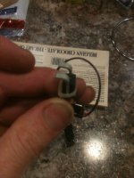
got around to install two new snubbers, this time a 4,7nf capacitor and 5x33R (6.6R) resistor.
this is what it looks like:
-2 (1).jpg")
max Voltage: 46v
this is what it looks like:
max Voltage: 46v
nieles said:yes i noticed that. i have the "old" (2.2nf snubbers) on 1 fet pair, the new snubbers on 1 fet pair, and then one pair not snubbed at all.
i had the scope on the fet pair without snubbers, and it looked a lot better than without any snubbers installed on all phases.
do you have any progress reports from other people working with your controller chip?
 I'm making a PCB now to make it easier
 liveforphysics said:First, props for typing on a Nintendo.
Second, I used to think this same thing. I learned I was mistaken when I made my big FET array for testing the A123 pouches. My gate waveform looked beautiful before it was under high current loading. The moment it was under load, it bounced all over hell and back, ringing the FETs a few dozen times for each switching cycle, and as I slid the welding clamp around on my bar of stainless serving as my variable load resistor, I could directly watch the amplitude, quantity of bounces, and duration of time it spent bouncing around increase in perfect sync with my load resistor decreasing resistance.
Going from 5ohm gate resistors to 22ohm gate resistors slowed the dI/dT slew rate of the FET conducting, which reduced the spikes by a huge amount, reducing the overall time the FETs were in the trans-conductance zone and the heat the FETs made by a huge amount. However, the 22ohm gate resistors made the switching look much slower and longer when the circuit was NOT under load. Lucky for my circuit, its goal wasn't to win an unloaded scope image waveform beauty contest, it was to function under load, and just adding 4x the gate resistance enabled it to work.
nieles said:lebowski,
i am doing some tests to get my controller running with the 6374 brushless motor smooth, and without cutting out to drive_0. i am experimenting with different values for Menu E option b,c and d. and also with different values for the IIR filter.
could you explain a little more about what the filter does, and what the effects are by changing to a higher or lower value (between 2 and 8 )
Lebowski said:Did you try following the calculations in the manual ? For my bike I followed them to the letter using y=256 and a 1 msec LR delay time.The filter should definately be more towards 8 than 2, I use 7 myself. I never had a cut-out to drive 0 with this setup (and I've done 150 km now).Also don't make menu d options f and g too small (shutdown error current levels), I have them both set at 2 A with a max phase amps of 16.
liveforphysics said:I used to think this same thing. I learned I was mistaken when I made my big FET array for testing the A123 pouches. My gate waveform looked beautiful before it was under high current loading. The moment it was under load, it bounced all over hell and back, ringing the FETs a few dozen times for each switching cycle, and as I slid the welding clamp around on my bar of stainless serving as my variable load resistor, I could directly watch the amplitude, quantity of bounces, and duration of time it spent bouncing around increase in perfect sync with my load resistor decreasing resistance.
Lebowski said:I wish i had access to the setup you're talking about, I bet somewhere in there you would find an LC oscillator in the small signal equivalent circuit.
I'll process the PCB as I am designing it now. I will order 2, one for my own development and one for a high power version (150V components and 150A current sensors)...
I still think though that gate resistors should only be used to dampen the ringing of the gate RLC, not to fix issues at the drian/source side. But let's see what the static experiments with the ME602 show....
When you dive in can you easily assemble a set up, preferably one that Lebowski can easily duplicate or verify, that resolves this discussion (one way or the other)?liveforphysics said:I've got your chip sitting right in the middle of my workshop bench.
As soon as I finish up the half dozen projects ahead of it, I'm diving in.
nieles said:when my new driver chips show up, i will try a 50ohm gate resistor and then gradually lower it until the spikes become too high.
what would be a safe time period until the miller plateau? i think i read somewhere bigmoose liked to have about 1us switch on/off times.
hopefully this will stop ruining my driver chips
I have wasted a lot of time for this very little step :|[00]
a] calibrate hall sensors
b] determine coil positions
c) PWM parameters
f) throttle setup
g) running modes
z) store parameters in EEPROM for motor use
------> a
a] number of e-rotations: 20
b] calibrate hall positions
c] table out hall signals
z] return to main menu
------> b
Spin the motor then press any key to start measurement
1
2
3
4
5
6
7
8
9
10
11
12
13
14
15
16
17
18
19
20
a] number of e-rotations: 20
b] calibrate hall positions
c] table out hall signals
z] return to main menu
------> c
hall 1, hall 2, hall 3
-.5000 .5200 -.5400
-.5000 .5200 -.5400
-.5000 .5200 -.5400
-.5000 .5200 -.5400
-.5000 .5200 -.5400
-.5000 .5200 -.5400
-.5000 .5200 -.5400
-.5000 .5200 -.5400
-.5000 .5200 -.5400
-.5000 .5200 -.5400
-.5000 .5200 -.5400
-.5000 .5200 -.5400
-.5000 .5200 -.5400
-.5000 .5200 -.5400
-.5000 .5200 -.5400
-.5000 .5200 -.5400
-.5000 .5200 -.5400
-.5000 .5200 -.5400
-.5000 .5200 -.5400
-.5000 .5200 -.5400
-.5000 .5200 -.5400
-.5000 .5200 -.5400
-.5000 -.5200 -.5400
-.5000 -.5200 -.5400
-.5000 -.5200 -.5400
-.5000 -.5200 -.5400
-.5000 -.5200 -.5400
-.5000 -.5200 -.5400
-.5000 -.5200 -.5400
-.5000 -.5200 -.5400
-.5000 -.5200 -.5400
-.5000 -.5200 -.5400
-.5000 -.5200 -.5400
-.5000 -.5200 -.5400
-.5000 -.5200 -.5400
-.5000 -.5200 -.5400
-.5000 -.5200 -.5400
-.5000 -.5200 -.5400
-.5000 -.5200 -.5400
-.5000 -.5200 -.5400
-.5000 -.5200 .5400
-.5000 -.5200 .5400
-.5000 -.5200 .5400
-.5000 -.5200 .5400
-.5000 -.5200 .5400
-.5000 -.5200 .5400
-.5000 -.5200 .5400
-.5000 -.5200 .5400
-.5000 -.5200 .5400
-.5000 -.5200 .5400
-.5000 -.5200 .5400
-.5000 -.5200 .5400
-.5000 -.5200 .5400
-.5000 -.5200 .5400
-.5000 -.5200 .5400
-.5000 -.5200 .5400
-.5000 -.5200 .5400
-.5000 -.5200 .5400
-.5000 -.5200 .5400
-.5000 -.5200 .5400
-.5000 -.5200 .5400
-.5000 -.5200 .5400
-.5000 -.5200 .5400
.5000 -.5200 .5400
.5000 -.5200 .5400
.5000 -.5200 .5400
.5000 -.5200 .5400
.5000 -.5200 .5400
.5000 -.5200 .5400
.5000 -.5200 .5400
.5000 -.5200 .5400
.5000 -.5200 .5400
.5000 -.5200 .5400
.5000 -.5200 .5400
.5000 -.5200 .5400
.5000 -.5200 .5400
.5000 -.5200 .5400
.5000 -.5200 .5400
.5000 -.5200 .5400
.5000 -.5200 .5400
.5000 -.5200 .5400
.5000 -.5200 .5400
.5000 -.5200 .5400
.5000 -.5200 .5400
.5000 -.5200 .5400
.5000 .5200 .5400
.5000 .5200 .5400
.5000 .5200 .5400
.5000 .5200 .5400
.5000 .5200 .5400
.5000 .5200 .5400
.5000 .5200 .5400
.5000 .5200 .5400
.5000 .5200 .5400
.5000 .5200 .5400
.5000 .5200 .5400
.5000 .5200 .5400
.5000 .5200 .5400
.5000 .5200 .5400
.5000 .5200 .5400
.5000 .5200 .5400
.5000 .5200 .5400
.5000 .5200 .5400
.5000 .5200 .5400
.5000 .5200 -.5400
.5000 .5200 -.5400
.5000 .5200 -.5400
.5000 .5200 -.5400
.5000 .5200 -.5400
.5000 .5200 -.5400
.5000 .5200 -.5400
.5000 .5200 -.5400
.5000 .5200 -.5400
.5000 .5200 -.5400
.5000 .5200 -.5400
.5000 .5200 -.5400
.5000 .5200 -.5400
.5000 .5200 -.5400
.5000 .5200 -.5400
.5000 .5200 -.5400
.5000 .5200 -.5400
.5000 .5200 -.5400
.5000 .5200 -.5400
.5000 .5200 -.5400
.5000 .5200 -.5400
.5000 .5200 -.5400
.5000 .5200 -.5400
.5000 .5200 -.5400
a] number of e-rotations: 20
b] calibrate hall positions
c] table out hall signals
z] return to main menu
------> z
a] calibrate hall sensors
b] determine coil positions
c) PWM parameters
f) throttle setup
g) running modes
z) store parameters in EEPROM for motor use
------> b
a] number of back-emf samples: 80
b] calibrate coil positions
c] reconstruct waveforms based on extracted parameters
d] table out data arrays
z] return to main menu
------> b
Spin the motor then press any key to start measurement
Sampling...
coil position capture failed
a] number of back-emf samples: 80
b] calibrate coil positions
c] reconstruct waveforms based on extracted parameters
d] table out data arrays
z] return to main menu
------> b
Spin the motor then press any key to start measurement
Sampling...
coil position capture successfull
data arrays now contain sampled back-emf waveforms
a] number of back-emf samples: 80
b] calibrate coil positions
c] reconstruct waveforms based on extracted parameters
d] table out data arrays
z] return to main menu
------> d
data A, data B, data C
.2375 .3967 .5696
.3801 .4806 .6887
.3801 .3662 .6776
.2375 .2365 .5845
.1425 .1182 .5063
.0000 .0038 .4207
-.1425 -.1220 .3239
-.2375 -.2441 .2420
-.3326 -.3509 .1712
-.4276 -.4501 .1042
-.5226 -.5302 .0558
-.5701 -.5989 .0148
-.6652 -.6484 -.0148
-.6652 -.6828 -.0297
-.7127 -.7095 -.0372
-.7127 -.7286 -.0446
-.8077 -.8544 -.1489
-.9503 -.9613 -.2382
-.9503 -.9956 -.2531
-.9978 -.9880 -.2345
-.9028 -.9155 -.1563
-.7602 -.8087 -.0409
-.7127 -.7133 .0558
-.5701 -.6027 .1675
-.2375 -.3433 .4318
-.1425 -.2593 .5212
-.0475 -.1792 .5919
.0475 -.1182 .6552
.0475 -.0762 .6925
.0950 -.0495 .7148
.1425 -.0305 .7297
.1425 -.0228 .7371
.2375 .1068 .8600
.3801 .2059 .9494
.4276 .2441 .9791
.4276 .2212 .9419
.3326 .1258 .8339
.1900 .0305 .7185
.0950 -.0572 .6143
-.0475 -.1525 .5063
-.1425 -.2517 .3872
-.2850 -.3318 .2829
-.4276 -.4310 .1377
-.4751 -.4806 .0484
-.5701 -.5226 -.0297
-.6177 -.5455 -.0856
-.6652 -.5569 -.1303
-.7127 -.5607 -.1675
-.7127 -.5531 -.2047
-.8077 -.6370 -.3239
-.9028 -.7133 -.4356
-.9503 -.7324 -.4951
-.9503 -.7133 -.5063
-.9028 -.6370 -.4616
-.8077 -.5187 -.3723
-.7127 -.4196 -.2978
-.6177 -.2937 -.2047
-.4751 -.1678 -.1079
-.3326 -.0495 -.0186
-.2375 .0610 .0632
-.0950 .1678 .1377
-.0475 .2479 .1898
.0475 .3166 .2308
.0475 .3662 .2457
.0950 .4005 .2494
.0950 .4272 .2457
.1425 .4882 .2717
.3801 .7362 .3723
.2850 .6332 .2382
.1425 .5378 .1154
.0475 .4615 .0111
-.0950 .3662 -.1154
-.2375 .2784 -.2308
-.3326 .1945 -.3425
-.4276 .1258 -.4356
-.5226 .0648 -.5249
-.5701 .0152 -.5919
-.6177 -.0190 -.6441
-.6652 -.0381 -.6776
-.7127 -.0534 -.7073
-.7127 -.0648 -.7297
-.8077 -.1678 -.8488
-.9503 -.2593 -.9494
-.9978 -.2899 -.9940
-.9978 -.2708 -.9829
-.9503 -.1869 -.9047
-.8077 -.0762 -.8041
-.7127 .0190 -.7148
-.5701 .1449 -.5957
-.1425 .5187 -.2457
-.0475 .5950 -.1675
.0000 .6484 -.1154
.0475 .6828 -.0819
.0950 .7019 -.0632
.0950 .7133 -.0484
.1425 .7553 -.0037
.2850 .9002 .1414
.3801 .9651 .2233
.4276 .9536 .2271
.3801 .8659 .1600
.1900 .7324 .0409
.0950 .6256 -.0446
-.0475 .5111 -.1340
-.1425 .3890 -.2345
-.2850 .2708 -.3201
-.3326 .2059 -.3648
-.4276 .1029 -.4318
-.5226 .0076 -.4914
-.6177 -.0686 -.5324
-.6652 -.1296 -.5584
-.7127 -.1716 -.5659
-.7127 -.2059 -.5659
-.7602 -.2365 -.5659
-.8552 -.3776 -.6701
-.9503 -.4920 -.7446
-.9978 -.5340 -.7520
-.9978 -.5264 -.7111
-.9028 -.4463 -.6031
-.8077 -.3509 -.4840
-.6652 -.2593 -.3685
-.5226 -.1487 -.2345
-.3801 -.0457 -.1079
-.2850 .0457 .0074
-.1425 .1258 .1116
-.0950 .1945 .2084
.0000 .2441 .2829
.0950 .2708 .3350
.0950 .2784 .3723
a] number of back-emf samples: 80
b] calibrate coil positions
c] reconstruct waveforms based on extracted parameters
d] table out data arrays
z] return to main menu
------> b
Spin the motor then press any key to start measurement
Back-EMF too small, spin motor faster and try again
coil position capture failed
a] number of back-emf samples: 80
b] calibrate coil positions
c] reconstruct waveforms based on extracted parameters
d] table out data arrays
z] return to main menu
------> b
Spin the motor then press any key to start measurement
Sampling...
coil position capture failed
a] number of back-emf samples: 80
b] calibrate coil positions
c] reconstruct waveforms based on extracted parameters
d] table out data arrays
z] return to main menu
------> b
Spin the motor then press any key to start measurement
Sampling...
coil position capture successfull
data arrays now contain sampled back-emf waveforms
a] number of back-emf samples: 80
b] calibrate coil positions
c] reconstruct waveforms based on extracted parameters
d] table out data arrays
z] return to main menu
------> d
data A, data B, data C
.1813 .3278 .4814
.0453 .1701 .3527
-.1360 -.0249 .1909
-.3174 -.1950 .0539
-.4534 -.3320 -.0622
-.5441 -.4523 -.1494
-.5895 -.5354 -.2033
-.6802 -.5810 -.2241
-.6802 -.6142 -.2365
-.8616 -.8217 -.4150
-.9523 -.9130 -.4772
-.9069 -.8840 -.4274
-.7709 -.7304 -.2490
-.6348 -.5810 -.0830
-.4534 -.4025 .1162
-.2720 -.2531 .2780
-.1360 -.1162 .4274
-.0453 -.0166 .5437
.0453 .0456 .6184
.0906 .0747 .6599
.1360 .0830 .6889
.2720 .2697 .8881
.4081 .3693 .9919
.3627 .2988 .9296
-.0453 -.1162 .5312
-.1813 -.2946 .3610
-.3174 -.4357 .2158
-.4534 -.5478 .0996
-.5441 -.6391 .0083
-.6348 -.6972 -.0498
-.6802 -.7263 -.0747
-.7255 -.8134 -.1660
-.9069 -.9753 -.3320
-.9523 -.9960 -.3610
-.8616 -.8923 -.2739
-.7255 -.7180 -.1162
-.5441 -.5395 .0456
-.3627 -.3610 .2116
-.2267 -.1992 .3527
-.0906 -.0581 .4648
.0453 .0539 .5437
.0453 .0871 .5644
.0906 .1411 .5852
.1360 .1784 .5893
.2720 .3569 .7304
.4081 .4980 .8425
.3627 .4689 .7802
.2267 .3112 .5935
.0906 .1826 .4274
-.0906 .0249 .2365
-.2720 -.1162 .0622
-.4081 -.2365 -.0871
-.4988 -.3320 -.2116
-.5895 -.3942 -.3029
-.6802 -.4274 -.3610
-.6802 -.4440 -.4025
-.8162 -.5810 -.5686
-.9069 -.6765 -.6931
-.9523 -.6516 -.6889
-.8162 -.5021 -.5644
-.6348 -.3278 -.4150
-.4988 -.1411 -.2531
-.3174 .0373 -.1037
-.2720 .1203 -.0332
-.1813 .1867 .0249
-.0453 .3195 .1245
.0453 .4191 .1992
.0906 .4772 .2241
.0906 .5146 .2324
.2267 .6682 .3610
.3627 .8134 .4814
.3627 .8051 .4482
.2267 .6474 .2697
.0906 .5146 .1037
-.0906 .3569 -.0788
-.2720 .2075 -.2531
-.4081 .0830 -.4025
-.4988 -.0207 -.5187
-.5895 -.0954 -.6059
-.6348 -.1328 -.6599
-.6802 -.1577 -.6972
-.7709 -.2822 -.8342
-.9069 -.4067 -.9753
-.9523 -.4025 -.9836
-.8616 -.2614 -.8549
-.6802 -.0996 -.7014
-.5441 .0747 -.5354
-.3627 .2490 -.3652
-.0453 .5686 -.0581
.0453 .6391 .0083
.0906 .6723 .0373
.0906 .6889 .0539
.2720 .9089 .2739
.3627 .9670 .3361
.3174 .8798 .2490
.1360 .6931 .0581
.0000 .5478 -.0871
-.1813 .3652 -.2614
-.3174 .2116 -.4025
-.4534 .0788 -.5187
-.5441 -.0332 -.6142
-.6348 -.0954 -.6599
-.6802 -.1452 -.6931
-.6802 -.1867 -.7138
-.9069 -.4025 -.9006
-.9976 -.4814 -.9462
-.9069 -.3735 -.7968
-.7255 -.2158 -.6059
-.5441 -.0622 -.4233
-.3627 .0954 -.2324
-.2267 .2324 -.0664
-.0906 .3444 .0830
.0453 .4150 .1867
.0906 .4482 .2490
.1360 .4565 .2863
.1813 .5520 .4108
.3627 .7138 .5935
.4081 .6848 .5893
.2720 .5229 .4482
.0906 .3569 .3029
-.0906 .1701 .1411
-.2267 .0000 -.0124
-.4081 -.1577 -.1411
-.4988 -.2822 -.2407
-.5895 -.3776 -.3154
-.6348 -.4357 -.3486
-.6802 -.4731 -.3610
.0000 .0000 .0000
a] number of back-emf samples: 80
b] calibrate coil positions
c] reconstruct waveforms based on extracted parameters
d] table out data arrays
z] return to main menu
------> c
data arrays now contain reconstructed back-emf waveforms
a] number of back-emf samples: 80
b] calibrate coil positions
c] reconstruct waveforms based on extracted parameters
d] table out data arrays
z] return to main menu
------> z
a] calibrate hall sensors
b] determine coil positions
c) PWM parameters
f) throttle setup
g) running modes
z) store parameters in EEPROM for motor use
------> z
a) write variables to EEPROM
z) return to main menu
------> a
Data stored in EEPROM for motor use
a) write variables to EEPROM
z) return to main menu
------> z
a] calibrate hall sensors
b] determine coil positions
c) PWM parameters
f) throttle setup
g) running modes
z) store parameters in EEPROM for motor use
------>ü[00]à[00]âø[00]äþüÿþ€þ[00][00]øà[01]ø[00]€¼8[00]@[00][00][1F]€þøøÀ[00][00][00][00]€[00][00][00][00]ÿ
a] calibrate hall sensors
b] determine coil positions
c) PWM parameters
f) throttle setup
g) running modes
z) store parameters in EEPROM for motor use
------>
a] calibrate hall sensors
b] determine coil positions
c) PWM parameters
f) throttle setup
g) running modes
z) store parameters in EEPROM for motor use
------> a
a] number of e-rotations: 20
b] calibrate hall positions
c] table out hall signals
z] return to main menu
------> b
Spin the motor then press any key to start measurement
1
2
3
4
5
6
7
8
9
10
11
12
13
14
15
16
17
18
19
20
a] number of e-rotations: 20
b] calibrate hall positions
c] table out hall signals
z] return to main menu
------> c
hall 1, hall 2, hall 3
-.5000 .5200 -.5400
-.5000 .5200 -.5400
-.5000 .5200 -.5400
-.5000 .5200 -.5400
-.5000 .5200 -.5400
-.5000 .5200 -.5400
-.5000 .5200 -.5400
-.5000 .5200 -.5400
-.5000 .5200 -.5400
-.5000 .5200 -.5400
-.5000 .5200 -.5400
-.5000 .5200 -.5400
-.5000 .5200 -.5400
-.5000 .5200 -.5400
-.5000 .5200 -.5400
-.5000 .5200 -.5400
-.5000 .5200 -.5400
-.5000 .5200 -.5400
-.5000 .5200 -.5400
-.5000 .5200 -.5400
-.5000 .5200 -.5400
-.5000 .5200 -.5400
-.5000 .5200 -.5400
-.5000 -.5200 -.5400
-.5000 -.5200 -.5400
-.5000 -.5200 -.5400
-.5000 -.5200 -.5400
-.5000 -.5200 -.5400
-.5000 -.5200 -.5400
-.5000 -.5200 -.5400
-.5000 -.5200 -.5400
-.5000 -.5200 -.5400
-.5000 -.5200 -.5400
-.5000 -.5200 -.5400
-.5000 -.5200 -.5400
-.5000 -.5200 -.5400
-.5000 -.5200 -.5400
-.5000 -.5200 -.5400
-.5000 -.5200 -.5400
-.5000 -.5200 -.5400
-.5000 -.5200 -.5400
-.5000 -.5200 -.5400
-.5000 -.5200 .5400
-.5000 -.5200 .5400
-.5000 -.5200 .5400
-.5000 -.5200 .5400
-.5000 -.5200 .5400
-.5000 -.5200 .5400
-.5000 -.5200 .5400
-.5000 -.5200 .5400
-.5000 -.5200 .5400
-.5000 -.5200 .5400
-.5000 -.5200 .5400
-.5000 -.5200 .5400
-.5000 -.5200 .5400
-.5000 -.5200 .5400
-.5000 -.5200 .5400
-.5000 -.5200 .5400
-.5000 -.5200 .5400
-.5000 -.5200 .5400
-.5000 -.5200 .5400
-.5000 -.5200 .5400
-.5000 -.5200 .5400
-.5000 -.5200 .5400
.5000 -.5200 .5400
.5000 -.5200 .5400
.5000 -.5200 .5400
.5000 -.5200 .5400
.5000 -.5200 .5400
.5000 -.5200 .5400
.5000 -.5200 .5400
.5000 -.5200 .5400
.5000 -.5200 .5400
.5000 -.5200 .5400
.5000 -.5200 .5400
.5000 -.5200 .5400
.5000 -.5200 .5400
.5000 -.5200 .5400
.5000 -.5200 .5400
.5000 -.5200 .5400
.5000 -.5200 .5400
.5000 -.5200 .5400
.5000 -.5200 .5400
.5000 -.5200 .5400
.5000 -.5200 .5400
.5000 -.5200 .5400
.5000 .5200 .5400
.5000 .5200 .5400
.5000 .5200 .5400
.5000 .5200 .5400
.5000 .5200 .5400
.5000 .5200 .5400
.5000 .5200 .5400
.5000 .5200 .5400
.5000 .5200 .5400
.5000 .5200 .5400
.5000 .5200 .5400
.5000 .5200 .5400
.5000 .5200 .5400
.5000 .5200 .5400
.5000 .5200 .5400
.5000 .5200 .5400
.5000 .5200 .5400
.5000 .5200 .5400
.5000 .5200 .5400
.5000 .5200 .5400
.5000 .5200 -.5400
.5000 .5200 -.5400
.5000 .5200 -.5400
.5000 .5200 -.5400
.5000 .5200 -.5400
.5000 .5200 -.5400
.5000 .5200 -.5400
.5000 .5200 -.5400
.5000 .5200 -.5400
.5000 .5200 -.5400
.5000 .5200 -.5400
.5000 .5200 -.5400
.5000 .5200 -.5400
.5000 .5200 -.5400
.5000 .5200 -.5400
.5000 .5200 -.5400
.5000 .5200 -.5400
.5000 .5200 -.5400
.5000 .5200 -.5400
.5000 .5200 -.5400
.5000 .5200 -.5400
.5000 .5200 -.5400
a] number of e-rotations: 20
b] calibrate hall positions
c] table out hall signals
z] return to main menu
------> z
a] calibrate hall sensors
b] determine coil positions
c) PWM parameters
f) throttle setup
g) running modes
z) store parameters in EEPROM for motor use
------> z
a) write variables to EEPROM
z) return to main menu
------> a
Data stored in EEPROM for motor use
a) write variables to EEPROM
z) return to main menu
------> z
a] calibrate hall sensors
b] determine coil positions
c) PWM parameters
f) throttle setup
g) running modes
z) store parameters in EEPROM for motor use
------> b
a] number of back-emf samples: 80
b] calibrate coil positions
c] reconstruct waveforms based on extracted parameters
d] table out data arrays
z] return to main menu
------> a
new value -> 900
a] number of back-emf samples: 900
b] calibrate coil positions
c] reconstruct waveforms based on extracted parameters
d] table out data arrays
z] return to main menu
------> b
Spin the motor then press any key to start measurement
Back-EMF too small, spin motor faster and try again
coil position capture failed
a] number of back-emf samples: 900
b] calibrate coil positions
c] reconstruct waveforms based on extracted parameters
d] table out data arrays
z] return to main menu
------> b
Spin the motor then press any key to start measurement
Sampling...
coil position capture failed
a] number of back-emf samples: 900
b] calibrate coil positions
c] reconstruct waveforms based on extracted parameters
d] table out data arrays
z] return to main menu
------> b
Spin the motor then press any key to start measurement
Back-EMF too small, spin motor faster and try again
coil position capture failed
a] number of back-emf samples: 900
b] calibrate coil positions
c] reconstruct waveforms based on extracted parameters
d] table out data arrays
z] return to main menu
------> b
Spin the motor then press any key to start measurement
Waiting for motor to slow down
Sampling...
coil position capture failed
a] number of back-emf samples: 900
b] calibrate coil positions
c] reconstruct waveforms based on extracted parameters
d] table out data arrays
z] return to main menu
------> b
Spin the motor then press any key to start measurement
Sampling...
coil position capture failed
a] number of back-emf samples: 900
b] calibrate coil positions
c] reconstruct waveforms based on extracted parameters
d] table out data arrays
z] return to main menu
------> b
Spin the motor then press any key to start measurement
Sampling...
coil position capture failed
a] number of back-emf samples: 900
b] calibrate coil positions
c] reconstruct waveforms based on extracted parameters
d] table out data arrays
z] return to main menu
------>
a] number of back-emf samples: 900
b] calibrate coil positions
c] reconstruct waveforms based on extracted parameters
d] table out data arrays
z] return to main menu
------> b
Spin the motor then press any key to start measurement
Sampling...
coil position capture failed
a] number of back-emf samples: 900
b] calibrate coil positions
c] reconstruct waveforms based on extracted parameters
d] table out data arrays
z] return to main menu
------> a
new value -> 90
a] number of back-emf samples: 90
b] calibrate coil positions
c] reconstruct waveforms based on extracted parameters
d] table out data arrays
z] return to main menu
------> b
Spin the motor then press any key to start measurement
Sampling...
coil position capture failed
a] number of back-emf samples: 90
b] calibrate coil positions
c] reconstruct waveforms based on extracted parameters
d] table out data arrays
z] return to main menu
------> b
Spin the motor then press any key to start measurement
Sampling...
coil position capture successfull
data arrays now contain sampled back-emf waveforms
a] number of back-emf samples: 90
b] calibrate coil positions
c] reconstruct waveforms based on extracted parameters
d] table out data arrays
z] return to main menu
------> d
data A, data B, data C
-.6302 -.4513 -.1867
-.6827 -.5310 -.2199
-.7878 -.6327 -.2282
-.7878 -.6637 -.2158
-.8928 -.7965 -.3029
-.9453 -.8850 -.3527
-.9453 -.8938 -.3278
-.9453 -.8451 -.2448
-.7878 -.7522 -.1286
-.7352 -.6637 -.0083
-.5777 -.5619 .1162
-.4201 -.4469 .2448
-.3151 -.3407 .3652
-.1575 -.2345 .4814
-.0525 -.1416 .5852
.0000 -.0752 .6682
.1050 -.0354 .7221
.1050 -.0177 .7553
.1575 -.0088 .7802
.1575 .0000 .8010
.2626 .1327 .9296
.3676 .1770 .9794
.0000 .0000 .0000
.3676 .1681 .9753
.3151 .1194 .9338
.2100 .0044 .8342
.1050 -.1194 .7263
-.0525 -.1991 .6474
-.1050 -.3186 .5395
-.2626 -.4336 .4274
-.3676 -.5398 .3237
-.5252 -.6460 .2241
-.5777 -.7257 .1452
-.6827 -.7920 .0830
-.7352 -.8274 .0415
-.7352 -.8451 .0083
-.7878 -.8496 -.0207
-.8403 -.9115 -.0996
-.8928 -.9823 -.1826
-.9453 -.9956 -.2158
-.9453 -.9558 -.2033
-.8928 -.8407 -.1286
-.7352 -.7080 -.0456
-.5252 -.4557 .1120
-.3676 -.3141 .2033
-.2626 -.1770 .2946
-.1050 -.0442 .3818
-.0525 .0663 .4440
.0525 .1548 .4855
.1050 .2124 .4980
.1050 .2610 .5021
.1050 .2876 .4855
.2100 .3849 .5437
.3151 .4956 .6101
.3151 .5265 .6101
.3151 .4911 .5437
.2100 .3894 .4150
.0525 .3009 .2988
-.0525 .2256 .1992
-.1575 .1239 .0705
-.3151 .0221 -.0622
-.4201 -.0752 -.1867
-.5252 -.1637 -.2988
-.6302 -.2301 -.3942
-.7352 -.2699 -.4689
-.7878 -.2832 -.5229
-.7878 -.2832 -.5852
-.8403 -.3141 -.6516
-.9453 -.3982 -.7678
-.9978 -.4159 -.8093
-.9978 -.3761 -.8051
-.8928 -.2743 -.7387
-.7878 -.1416 -.6474
-.6827 -.0221 -.5686
-.5252 .1194 -.4689
-.4201 .2522 -.3693
-.2626 .3894 -.2656
-.1575 .5133 -.1660
-.0525 .6106 -.0913
.0525 .6814 -.0415
.1050 .7301 -.0124
.1050 .7611 .0041
.1050 .7788 .0000
.2100 .8673 .0705
.2626 .9602 .1452
.3151 .9779 .1577
.2626 .9248 .0996
.2626 .8850 .0622
.1050 .7522 -.0664
-.0525 .6637 -.1577
-.1050 .5664 -.2531
-.2100 .4513 -.3735
-.3676 .3363 -.4814
-.4726 .2212 -.5893
-.5777 .1327 -.6723
-.6827 .0575 -.7429
-.7352 .0088 -.7885
-.7878 -.0221 -.8134
-.7878 -.0398 -.8300
-.7878 -.0708 -.8549
-.9453 -.1947 -.9545
-.9978 -.2522 -.9919
-.9978 -.2478 -.9670
-.9453 -.1725 -.8798
-.7878 -.0619 -.7595
-.6827 .0309 -.6516
-.5777 .1371 -.5229
-.4201 .2478 -.3942
-.3151 .3451 -.2614
.0000 .5664 .0664
.1050 .5885 .1245
.1050 .5929 .1660
.1050 .5796 .1909
.1575 .6195 .2656
.3151 .7124 .3984
.3151 .7124 .4357
.3151 .6460 .4025
.1575 .5088 .3029
.0525 .3717 .2075
-.0525 .2743 .1369
-.1575 .1327 .0332
-.3151 .0000 -.0664
-.4201 -.1283 -.1535
-.5252 -.2478 -.2365
-.6302 -.3451 -.2988
-.7352 -.4203 -.3320
-.7352 -.4690 -.3486
-.7878 -.5088 -.3527
a] number of back-emf samples: 90
b] calibrate coil positions
c] reconstruct waveforms based on extracted parameters
d] table out data arrays
z] return to main menu
------>