Lebowski's motor controller IC, schematic & setup, new v2.A1

Tomdb said:
would adding a set regen pot on throttle two fix this you think? Or should I measure my phases to see if its safe to up the pwm freq?
No, the internal throttle closes but the motor keeps running, a second pot won't fix that.

What you can try is to add some inductance in series with each of the 3 motor wires, this will also reduce pwm currents. With some thick wire wind 3 equal inductors and place in series with motor. You need to re-run the Foc calibration, which will then also sowh you how much inductance was added.
 
I will measure first. Log the battery current and then slowly increase pwm frequency. Igbts should easily be safe at a little higher pwm up to like 6 khz.

Maybe i can google some to try and find honda's original pwm frequency.

Update

Couldnt find the pwm frequency got a lot of nice documents on EV drive development though and research. So i measured battery current, from 4 khz to 5khz it dropped about 1 amp. Which sounds like a good thing. And the throttle response is working as it should now :D

Now again at that point where i need a vehicle to start testing with.

My current settings:

Code:
0x00BD	0x092F	0x0001	0xE2A1	0x0530	0x0530	0x085A	0x0035
0x001A	0x0026	0x7FBC	0x011C	0x0000	0x0047	0x8000	0x0164
0x00B2	0x02A3	0x03F3	0x03F3	0x03F5	0xAAAA	0xAAAA	0xAAAA
0x0BB7	0x0248	0x008F	0x02DA	0x000B	0xE676	0x0380	0xFFFF
0xFFFF	0xFFFF	0x1000	0x0000	0x0000	0xFFFF	0xFFFF	0x016B
0x01F4	0x0590	0x0047	0x0590	0x0590	0x0804	0x0258	0x0064
0xFFFF	0xFFFF	0xFFFF	0xFFFF	0x0000	0x999A	0x0030	0x0000
0x01E0	0xFFFF	0x6666	0xFFD0	0x0000	0xFE20	0x0000	0x07AE
0x0030	0x0000	0x01E0	0xFFFF	0xF852	0xFFD0	0x0000	0xFE20
0x0003	0x0000	0x0078	0x0000	0x0000	0xFFFD	0x0000	0xFF88
0x0000	0x0000	0x0000	0x0000	0x0003	0x0000	0x00C8	0x0000
0x0000	0xFFFD	0x0000	0xFF38	0x0000	0x0000	0x000C	0x0000
0x00F0	0x0000	0x0000	0xFFF4	0x0000	0xFF10	0x05CC	0x0094
0x0204	0x0907	0x01AB	0x0035	0x00E4	0x7530	0x013E	0x0007
0x03BA	0x0042	0x0010	0x1554	0x0000	0x03E8	0x00C8	0x5043
0x03B6	0x6000	0x011C	0x013F	0xFFFF	0xFFFF	0xFFFF	0xFFFF
0xFFFF	0xFFFF	0xFFFF	0xFFFF	0x4000	0xFFFF	0xFFFF	0xFFFF
0xFFFF	0xFFFF	0xFFFF	0xFFFF	0xFFFF	0xFFFF	0xFFFF	0xFFFF
0xFFFF	0xFFFF	0xFFFF	0xFFFF	0xFFFF	0x0000	0x0000	0x0000
0x0032	0xFFFF	0xC519	0x764B	0x5482	0x41B3	0x35C3	0x2D7A
0x276B	0x22C9	0x1F1E	0x1C28	0x19B5	0x17A6	0x15E6	0x1463
0x1312	0x11EB	0x10E4	0x0FFB	0x0F28	0x0E6B	0x0DC0	0x0D23
0x0C94	0x0C10	0x0B97	0x0B27	0x0ABF	0x0A5F	0x0A05	0x09B1
0x0962	*
 
Now that it seems to work, can you maybe share some picture of your setup, of the honda module, schematic ? Where did you get the module from ? What kind of ratings and power can you get from this module ?

I think a controller based on a cheap all inclusive power module would be interesting go a lot of people here.... so please more info !
 
Lebowski said:
Now that it seems to work, can you maybe share some picture of your setup, of the honda module, schematic ? Where did you get the module from ? What kind of ratings and power can you get from this module ?

I think a controller based on a cheap all inclusive power module would be interesting go a lot of people here.... so please more info !
Yup modding a insight would be cool
 
Made a document with my findings. Its the second gen ima.
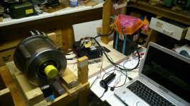
Also my setup, got a cad model of the inverter if anyone is interested.
 

Attachments

  • Honda Ima electric 2.1.pdf
    1 MB · Views: 96
Arlo1 said:
Ok My serial port won't show up in labview.

Moving on. I went through all the other items on my list and got my leaf inverter running perfectly on the bench all the way up to max voltage (458v close enough for bench testing) Video to come with a post in my thread.
I just had to change a few simple things for recovery and a few other things then I found I could not go full throttle in drive 2 (hall sensored) so I kept trying the simple things like eRPM and how many cycles etc. But I could not get it to work right with those settings so I messed around in the control loop coefficients and eventually looking at the manual I found I think you made a error.

The autocomplete sends
E to 480
F to 48
G to .0299

In the manual you say
This automatic advance comes
on top of the advance of coefficient c,f. For stability d,g must be less than 1/40th of c,f.
But 48/40 = 1.2 not .0299.... So I just shifted G a order of magnitude up to .3 and it worked perfectly!
Now I might even want to go to below 1.2..... ? For now it runs on the bench so I'm not worried but once I put a load on it I might want to look at this again.

Yep, you are right, the 0.3 is much better than the 0.03 ... The autocomplete value of 0.03 is done for the sensorless start, it prevents the controller from updating the speed variable
too fast and thus from hopping between drive 2 and 3 in sensorless. For hall start however the low 0.03 is not necessary so the 0.3 is better.
 
OK so that's good to know if I need to do another sensor-less start I will set it back to the auto correct settings.
 
I tried driving it a little bit with a low current setting and it was konking out in drive 2. I didn't have any time to mess with settings but should I try messing with option g further?
I set it to 1 but never tried it under load.
I then put the wheels in the air and checked some things.
I don't have recovery working is there something I should change to make it work better?
I also found if I give it full throttle It lights up D 2 led and D 3 led at the same time when Its trying to transition and it seems to take a long time to transition under full throttle.
If I let off the throttle when Both LEDs are on it will loose sync and go back to D1 but does not recover.
See my leaf thread for a video.

What settings should I play with? I will try tomorrow night to see if I can make it better. I just tried driving it ~8 feet back and forth in the shop because we were getting a down pour out side.
Code:
0x0CA6  0x031C  0x005F  0x6556  0x13E8  0x13E8  0x200E  0x0061                  
0x000C  0x0006  0x7FBC  0x007F  0x0000  0x0020  0x8000  0x009F                  
0x004F  0x012E  0x03B2  0x039F  0x03A2  0xAAAA  0xAAAA  0xAAAA                  
0x0BB8  0x0BB8  0x008F  0x0D05  0x0003  0xE67C  0x1CA0  0x1199                  
0x0000  0x0000  0xFE66  0x0000  0x0000  0x002B  0x03D4  0x0000                  
0x03FF  0x027E  0x005B  0x0223  0x0111  0x01C0  0x0258  0x0064                  
0x0004  0x0004  0x000E  0x0298  0x0000  0x999A  0x0030  0x0000                  
0x01E0  0xFFFF  0x6666  0xFFD0  0x0000  0xFE20  0x0001  0x0000                  
0x0030  0x0000  0x01E0  0xFFFF  0x0000  0xFFD0  0x0000  0xFE20                  
0x0003  0x0000  0x0078  0x0000  0x0000  0xFFFD  0x0000  0xFF88                  
0x0000  0x0000  0x0000  0x0000  0x0003  0x0000  0x00C8  0x0000                  
0x0000  0xFFFD  0x0000  0xFF38  0x0000  0x0000  0x000C  0x0000                  
0x00F0  0x0000  0x0000  0xFFF4  0x0000  0xFF10  0x01DB  0x1075                  
0x01C9  0x05B0  0x02AB  0x00F3  0x0411  0x7530  0x05B0  0x0024                  
0x06D2  0x0042  0x0010  0x0E10  0x0000  0x05DC  0x0190  0x1194                  
0x03B6  0x6000  0x00B6  0x05B2  0xFF00  0xDC3F  0x323F  0x073F                  
0x873F  0xB23F  0x5C3F  0xFF00  0x4000  0xFFFF  0xFFFF  0xFFFF                  
0xFFFF  0xFFFF  0xFFFF  0xFFFF  0xFFFF  0xFFFF  0xFFFF  0xFFFF                  
0xFFFF  0xFFFF  0xFFFF  0xFFFF  0xFFFF  0x0000  0x2483  0x0032                  
0x0005  0xFFFF  0xC519  0x764B  0x5482  0x41B3  0x35C3  0x2D7A                  
0x276B  0x22C9  0x1F1E  0x1C28  0x19B5  0x17A6  0x15E6  0x1463                  
0x1312  0x11EB  0x10E4  0x0FFB  0x0F28  0x0E6B  0x0DC0  0x0D23                  
0x0C94  0x0C10  0x0B97  0x0B27  0x0ABF  0x0A5F  0x0A05  0x09B1                  
0x0962  *
 
The settings look OK except for the error currents all being very low. Your sensors are 1.85mV/A, so 17.4A error current means it will only tolerate around 30mV of noise.

That D2 and D3 are on at the same time is also telling... when going from D2 to D3 it passes through an intermediate mode when both 2 and 3 are on. In this mode it still uses
the relaxed error settings of D2 but the control loop coefficients of D3. It will exit this mode to D3 when the error current is 1/8 of the fixed error current setting (menu b option j).
In your case with the low 17.4A setting it never sees only 17.4/8 = 2 A error current (less than 4mV noise, practically impossible also because the ADC has a 5mV resolution).

So, set the max phase amps to 300A or so and autocomplete the currents menu and the recovery menu, this will give more realistic error current settings more fitting to your sensors.
Then set the max phase current back to 50A or whatever low value you want.

When you apply regen with the motor standing still, it will shudder a bit as this is an unstable condition (with regen you ask for negative phase amps which normally counteracts
forward rotation, but when standing still will give a shudder as negative phase amps also means to start rotating in reverse). The controller hops between negative phase amps (which
will want to make a reverse rotation) and realizing that reverse is not allowed as forward is selected.
 
Ok thanks I will try that tonight.... I will also look at a way to shut off the regen at a stand still.... Maybe a time-out on arduino....
 
Okay, playing with the small motor was just to prove to myself it would work. Designed a pcb so I can mount it inside the inverter the lewboski chip that is.

Got myself a motor which I will use for a later project. It is an bldc motor, roughly 60kw continuous in its previous application. Now the big issue I ran into, using my previous known working config, I decided to run the FOC setup. Does two tones then the controller freezes/locks up a reset brings it back to the menu.
Any idea on if any settings need to be changed, or could it be due to EMC from the huge motor and phase leads? Since I changed nothing on the inverter side, im leaning to the "test cut trace" pcb which it is on now, unless there are some settings im overlooking.

DSC_029622.jpg

DSC_029500.jpg
 
Tomdb said:
Okay, playing with the small motor was just to prove to myself it would work. Designed a pcb so I can mount it inside the inverter.

Got myself a motor which I will use for a later project. It is an bldc motor, roughly 60kw continuous in its previous application. Now the big issue I ran into, using my previous known working config, I decided to run the FOC setup. Does two tones then the controller freezes/locks up a reset brings it back to the menu.
Any idea on if any settings need to be changed, or could it be due to EMC from the huge motor and phase leads? Since I changed nothing on the inverter side, im leaning to the "test cut trace" pcb which it is on now, unless there are some settings im overlooking.

View attachment 1

You are planning to put a 60kw pcb inside that motor?
 
No, the motor it self is rated at that. Switching Inverter once I get my project vehicle, pcb for the controller will go inside the inverter housing, to make it look more OEM. :wink:
 
Tomdb said:
No, the motor it self is rated at that. Switching Inverter once I get my project vehicle, pcb for the controller will go inside the inverter housing, to make it look more OEM. :wink:
So how powerful do you plan to make the inverter that is inside the motor housing? I am asking because I like the idea but its not good to have one put heat into the other. So keeping it cool is key.
As well I am excited to find out the power density of the internal inverter.
 
No, you are missing my point. Im not building one inside the motor, might look into making one that bolts to the side of the motor. Like tesla has, but without an gearbox between.

Im planning on getting an Chevy Volt inverter and placing my own lebowski pcb inside the Chevy volt inverter.
 
Tomdb said:
No, you are missing my point. Im not building one inside the motor, might look into making one that bolts to the side of the motor. Like tesla has, but without an gearbox between.

Im planning on getting an Chevy Volt inverter and placing my own lebowski pcb inside the Chevy volt inverter.
Ok thats super cool :)
 
Hm, the FOC measurement failing doesn't typically happen, he only way I've seen it fail is when the power source cannot deliver enough power and collapses.. but that doesn;t seem likely in your case (I have a 65V 2.5A source which can conk out, but a battery...) . Are you sure the 5V on the brain is stable ? Are there enough capacitors (both 100nF ad 47uF) around the brain (it can lock up in a funny way if there are not enough of them) ?

You say it does two tones, you mean it does a tone for 3 seconds and then seems to start over and does it again for 3 seconds ? That is new for the versions with field weakening, it does the same measurement twice in a row but with different deadtimes, to get a more accurate reading for the motor resistance. If it manages the first one OK (double deadtime) and conks out during the second one (normal deadtime), is your deadtime OK ? But it works for the small motor so deadtime should be ok...

What happens here sometimes is that my laptop locks up because of a spike over the RS232, I have to unplug the usb<->rs232 to get it working again.

If all seems OK, PM me the hex and I will try to replicate the situation...
 
I will try the unplugging the usb and plugging it in again. However, if I reset the controller and send a keystroke to it, without resetting anything else it shows the setup menu.
Yes it does the measurement twice, 3 seconds one tone and then again.
 
Did some testing. The Hex on the micro is posted below.
I set the option for measurement current lower, this caused a lower "amplitude" tone. So It seems that the current settting is working, however the micro still locks up after the test. I would think this to be a wierd time for the controller to lock up, as its not doing anything with inputs and outputs.

Tested the usb converter theory of it locking up, however this does nothing. The reset always has to be done on the micro to get communication working again.

Should have my pcb in soon, designed it with ground and power planes and smd caps close to the pins. If it is an 5v supply issue that should solve it.

Code:
0x00BD	0x092F	0x0001	0xE2A1	0x0744	0x0744	0x0BB3	0x0035
0x001A	0x0026	0x7FBC	0x011C	0x0000	0x0047	0x8000	0x0164
0x00B2	0x02A3	0x03F3	0x03F3	0x03F5	0xAAAA	0xAAAA	0xAAAA
0x0BB7	0x0248	0x008F	0x02DA	0x000B	0xE676	0x0380	0xFFFF
0xFFFF	0xFFFF	0x1000	0x0000	0x0000	0xFFFF	0xFFFF	0x016B
0x01F4	0x0590	0x0047	0x07CA	0x0590	0x0804	0x0258	0x0064
0xFFFF	0xFFFF	0xFFFF	0xFFFF	0x0000	0x999A	0x0030	0x0000
0x01E0	0xFFFF	0x6666	0xFFD0	0x0000	0xFE20	0x0000	0x07AE
0x0030	0x0000	0x01E0	0xFFFF	0xF852	0xFFD0	0x0000	0xFE20
0x0003	0x0000	0x0078	0x0000	0x0000	0xFFFD	0x0000	0xFF88
0x0000	0x0000	0x0000	0x0000	0x0003	0x0000	0x00C8	0x0000
0x0000	0xFFFD	0x0000	0xFF38	0x0000	0x0000	0x000C	0x0000
0x00F0	0x0000	0x0000	0xFFF4	0x0000	0xFF10	0x05CC	0x0094
0x0204	0x013E	0x02C8	0x0035	0x00E4	0x7530	0x013E	0x0007
0x03BA	0x0042	0x002F	0x0E10	0x0000	0x03E8	0x00C8	0x5043
0x03B6	0x6000	0x011C	0x013F	0xFFFF	0xFFFF	0xFFFF	0xFFFF
0xFFFF	0xFFFF	0xFFFF	0xFFFF	0x4000	0xFFFF	0xFFFF	0xFFFF
0xFFFF	0xFFFF	0xFFFF	0xFFFF	0xFFFF	0xFFFF	0xFFFF	0xFFFF
0xFFFF	0xFFFF	0xFFFF	0xFFFF	0xFFFF	0x0000	0x0000	0x0000
0x0032	0xFFFF	0xC519	0x764B	0x5482	0x41B3	0x35C3	0x2D7A
0x276B	0x22C9	0x1F1E	0x1C28	0x19B5	0x17A6	0x15E6	0x1463
0x1312	0x11EB	0x10E4	0x0FFB	0x0F28	0x0E6B	0x0DC0	0x0D23
0x0C94	0x0C10	0x0B97	0x0B27	0x0ABF	0x0A5F	0x0A05	0x09B1
0x0962	*
 
added some more caps. Here is an overview of my setup right now, I listed the large caps. Smaller ones are 100nF
 

Attachments

  • DSC_029800.jpg
    DSC_029800.jpg
    189.8 KB · Views: 1,586
I think you barely have enough cap there...

First off, on the top right are the inputs from the current sensors,,, did you go to 100 Ohm and 100 nF ? this would be OK, but 1 kOhm and 100 nF is not OK, with 1k you need only 10 nF

On the top left you have no caps after the 10 Ohm going in to the analog supply of the chip ? There is a good chance this analog voltage is used for the brown out detection which is set pretty tight at 4.7V...

In the middle two sets of supplies (pins 11, 12, 31, 32) you have caps but I cannot see whether you also have caps at pins 20 and 21 ?

I;m probably erring on the cautious side but I have like 10 sets of 47uF and 100nF all over my PCB...

woops, just saw chip is upside down. Still, are there caps on the analog supply after the 10 Ohm and are there caps on all 4 supply sets ?
 
Thanks for the reply.

Current sensors are 1K resistor and 10nF cap.
I will add more caps, have plenty in my parts bin doing nothing.

Wierd that with the small motors there were no issues. :?
 
Added 100uf and 100nf to the Power in pin 21 and 20. And an 100nf to 11,12 and 40,39. Still no luck. hooking my scope up to the 5volt is a bit of an hassel right now, I do not have any IC test clips.

Hoping my custom pcb from Itead arrives soon so I can solve this issue with an proper board instead of my experiment print with loose wires on the back.
 
Back
Top