J0nathan
1 mW
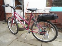
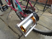
My mum recently asked me to make an e-bike for her to use, just for short trips. A long time ago I bought one of the large turnigy 130kV motors, intending to use it on my own bike however I never got round to it. More recently someone gave me a bike conversion kit with a broken controller. Unfortunately the controller is built into the BLDC motor and potted with epoxy, so I've left that for now. The kit comprised of this motor connected to a planetary gearbox and chain, which attaches to the rear wheel, so I just made a new shaft for the turnigy motor and mounted it to the gearbox by making an appropriate aluminium adapter plate. As you can see in the images below, I machined some aluminium bars and another plate to help protect the motor in case the bike falls over. It's powered by two 5Ah Zippy 20C 6s batteries in parallel to give 22.2V and 10Ah.
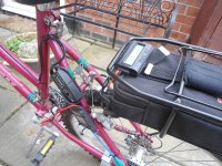
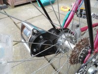
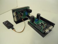
It was all going well the few times I tested it - 20.1Wh/mile at an average speed of 12.7 mph and top speed 17.6 mph. Slow by most people's standards here, but plenty fast enough for my mum! The first time she tried it without me, the ESC went pop. I'm not entirely sure what caused it. Apparently a capacitor touched the bike frame and made a reasonably loud noise, so the most plausible explanations is that it short circuited with the motor via the ESC, however none of the motor wires appeared to be touching the bike frame so I'm not sure. The meter registered a peak of 64A, which is less than I've seen in normal operation. It's quite annoying since although it was a cheap ESC from a long time ago, it did seem quite robust as it uses TO-220 mosfets, not the usual masses of silly little things. I tried replacing the pair of mosfets that had clearly blown, but it didn't make a difference - the motor just twitches and draws quite a high current so I think one of the gate drivers is probably at fault.
It seems sensible to replace this with a sensored controller and from reading around on this forum it looks like the following parts would work well:
http://www.ebay.com/itm/48V-600W-brushless-controller-for-E-bike-scooter/300352534034
http://uk.farnell.com/jsp/displayProduct.jsp?sku=3111465&CMP=KNC-GUK-FUK-GEN-SKU-MDC&mckv=s8W87YpR5|pcrid|19854174608|kword|ss411a|match|p|plid|
I'll happily replace the mosfets with IRFB4110 (or whatever), if required. As you can see in the pictures I have separated the wires in the motor, so I can easily wire it in star or delta, so I think the best option would be to change it from delta (current setup), to star, then put the batteries in series instead of parallel. That should raise the top speed by about 15%, but more importantly should make the system more efficient since the currents will be lower. Can anyone tell me if this plan is reasonable and if the controller I linked to is a sensible choice?


