
steveo
100 kW
ITS THAT SIMPLE....
i will try it out on the weekend and let you know if it works..
-steveo 8)
i will try it out on the weekend and let you know if it works..
-steveo 8)


")
GGoodrum said:Very cool. 8) The version on my wife's bike is still going strong. It provides a whole lot better braking than the rear hub brake in the Nexus 8 hub, especially at higher speeds. The faster you are going, the more braking power you get, which I think is perfect.
-- Gary
fechter said:OK, here is the simplest possible configuration:
By only tapping two motor wires and no bridge, the braking current will be only passing through 2 of the 3 motor windings.
If you were doing really long downhills, it could possibly cause the motor windings to overheat, but with an X5 motor, overheating would be pretty hard.
The two coil configuration can evenly spread the load in the motor windings, but requires an additional switch contact. This may be unnecessary.
The length of wire in the resistor coil depends on what kind of motor you're running and your top speed. A 5303 will need fewer turns, a 5304 or 05 will need more turns.
diver said:with that much of a resistor even if the brake and throttle were engaged at the same time accidental, it would not harm the controller, am i right thinking this ?


Dr. Shock said:Would this work equally well on a brushed motor? Simply switch the motor wires into a big resistance coil?
fechter said:The "new and improved" regen setup avoids using the bridge by using a brushed controller that has 6 FETs (it's what I had lying around). Something with 3 FETs would work too.
The FETs are normally all in parallel in a brushed controller, so I separated the drains and kept the sources connected to ground. Other than that, it is the same as the bridge rectifier setup. The advantage is there is no bridge, which would not perform well under switching conditions, so the amount of power actually recovered to the batteries would be more. A bridge rectifier would need a large heat sink, which would be eliminated by going direclty to the FETs.
lazarus2405 said:So, let's see if I understand this. The brushed controller has a bunch of parallel mosfets used to PWM the battery current into various DC voltages dependent upon the throttle signal and then the PWM gate driver. In normal operation, all the gates are connected in parallel to the driver, all the sources are connected to the battery, and all the drains are connected to the motor. The throttle governs how the MOSFETS modulate the voltage to the motor, thus controlling the motor's speed.
Erm, wait... these controllers do the controlling on the negative side of the circuit... I may have mixed up the sources and drains? Please correct as needed.
In our modification, we're running things backwards. We're disconnecting the drains of three of the FETs from the controller and connecting our motor phase wires to that. The source is connected to ground, which is the controller's battery negative. Then those three FETs are used to rectify the 3-phase AC into high-voltage DC, drawing more or less current based on the PWM signal based on the throttle.
I think you got it pretty much right. Inside the brushed controller, the M+ and B+ wires are connected. The FET drains go to the motor, and the sorces are grounded.
The general configuration looks like this: The B+ and B- wires go to the battery. Very little current will go through these, so the wires don't need to be big. The motor (-) buss is chopped into 3 parts and phase wires attached to each part.
When the FETs turn on, they all turn on at the same time because the gates are still tied together. This shorts out the motor windings. When the FETs open, the collapsing magnetic field will circulate current back through the body diodes in the main controller. The freewheel diodes in the braking controller won't be doing anything, so they can be removed. The PWM duty cycle of the braking controller will determine the amount of braking.
When the braking controller is off, all the FETs are open, so there is no drain on the main controller.
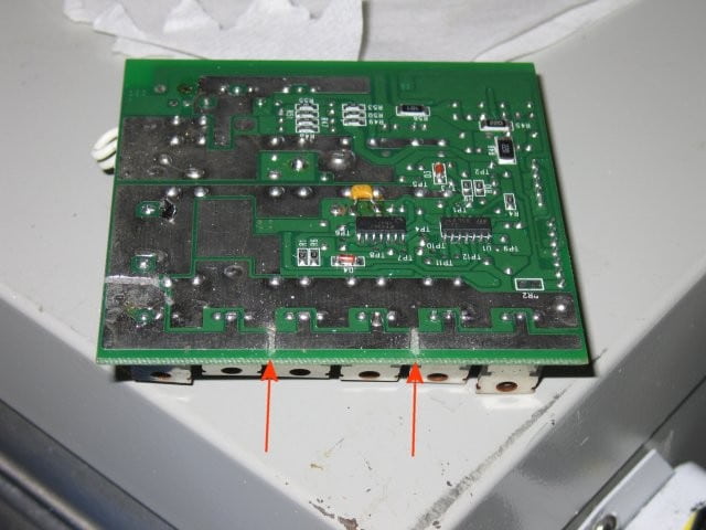
fechter said:Here's my test unit before

I then cut the motor- buss into 3 segments with a dremel tool:
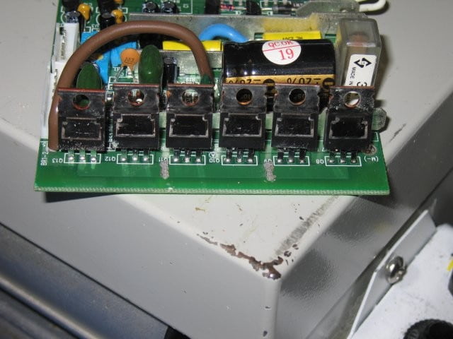
Then I added wires to each of the 3 segments to bring out to the phases:

fechter said:When the regen controller shorts out the windings, current flows through it. When the PWM opens the switches, there's nowhere for the voltage to go execpt through the body diodes in the main controller, back into the batteries. If the CA is in series with the batteries, it will read the regen current. Even at very low speeds, you will get regen back into the batteries. The regen current will be passing from the motor back through the main controller (even though it's off).


GGoodrum said:With the wire coil-type ebrake, you get proportional braking, based on speed. The faster you are going, the greater the braking power. My point is that you don't need a bunch of different taps/switches.
-- Gary