Make: Fechters' Braking Regen Add-on for BLDC Motors

fechter said:
The "pot box" setup with a switch would work.

Are you using that in a broad sense, where the "pot box" in this case has no pot? Because as far as I can tell the YKxx line won't take pot throttles. Would a linear hall effect sensor work, and can they be bought in the way I'd want to use it? Or would I need to make my own with a Hall sensor and magnets?

The way I'm thinking of wiring it on my scooter...

You mean this one? http://www.evalbum.com/803 :p


-- Does the most recent circuit have any provision to adjust the charge rate so the pack will receive the optimal current for charging and longevity?

Yup! The idea is to used a brushed motor controller to control the regen, to use its throttle to adjust the braking force, and to use its current limit to protect the batteries. That way, turning the regen controller's throttle will increase the current going to the batts until it reaches the current limit, which would have to be manually set for each battery.

The idea I'm liking is to use the regen 80% of the time for braking, and the resistor coil either when the batts are at a full charge or when the stopping power needed would generate more current than the batts could handle. Also, redundant brakes are really underrated.

Also... when I build my regen brake, should I use this thread, or make a brand new build thread for it? I mean, this one has a lot of information, but it forces one to dig to the 5th page to find the most recent circuit.
 
lazarus2405 said:
Are you using that in a broad sense, where the "pot box" in this case has no pot? Because as far as I can tell the YKxx line won't take pot throttles. Would a linear hall effect sensor work, and can they be bought in the way I'd want to use it? Or would I need to make my own with a Hall sensor and magnets?

You could use either a pot or a hall sensor with a magnet. To use a pot, you just need a couple of fixed resistors on either side to make the output go from about 1v to 4v.

I've never seen a linear hall setup, but you could use a standard hall throttle, since it only rotates about 90 degrees.

Yes, that's my scooter. More here: http://endless-sphere.com/forums/viewtopic.php?f=12&t=582


If you look at the duct tape battery thread, you'll see its 50 pages long! If you want to start a new thread, that's fine to me. I have no preference.

I have most of the wiring done on my test unit. I just need to tie in the phase wires. I'm not going to use any fuses for initial testing, but fuses in the phase wires would be a good idea. If the crapola IRFZ48's in my brushed controller decide to short, it will likely take out the FETs in my main controller instantly if I give it throttle.
 
I just implemented the electromotive braking circuit (in which motion is converted to waste heat) but I'm not sure if I did it right. I only went for a quick run just now at 20-25 mph, and when I push the switch, there's a very slight deceleration and a definite buzzing that I can hear and feel. I used 22-gauge wire with a momentary push-switch from RadioShack (max 3A at 125VDC so 375W I guess); I used a 5-foot wire from the switch to one phase wire and a 20-foot length from another phase wire to the switch. The 20' length is wound around the bike frame, though I think there may be overlapping loops; they're not all parallel. I was lazy. Does that matter? The 5' length was also wound slightly at the same location just to remove slack.

I'm using a 5303. Did I simply use too much wire, or are the loops the problem, or what? And is the buzzing a sign that something is wrong?
 
First off, I am not convinced that switch will work at all, or for very long. It'll be seeing a lot more than 3 amps, so it might just blow on you. If you needed the brakes then, well you'd be one sad panda. It would be wise to use a larger switch rated for more current. RS might have momentary switches that can do it, but the one I went to did not. Though, they had several toggle switches rated for 10a and 20a.

A better solution, though, is to use a relay. Get rid of that extra 5 feet going to the handlebar and connect the coil to the relay. Then run wire from the relay up to the handlebars. Take the switch you have and wire it and a power source to the relay. Then, when you push the little button, it'll activate the relay, which will use its much larger contacts to close the resistor circuit. Now, the only problem I have with this setup is that I don't know what to use to power the relay. It takes a small bit of current to keep it closed, so I would need to tap maybe a 5v line from the controller. Fechter would have a good suggestion for that.

It looks like the coil is just too long. Take out that 5' length and test at a few different speeds, then keep shortening it until you're happy.
 
Bah, that's pointlessly complicated. The elegance of a normal switch is that the batteries and controller are irrelevant -- braking energy is 100% supplied by the forward motion of the bike.

Instead I figure I'll use the 60A 12V button second from the bottom on this page. Oh, and a front disc brake is my primary brake. I have the button positioned so I can put my thumb on it and squeeze the brake lever at the same time if I want to.

The 5' length still has to go from the switch to the rear motor so there's really only like 1' of slack. I suspect you're right and I have to remove some wire, in which case it'll be the 20' length I trim. Still not sure about that buzzing though.
 
If any of the coils are loose, they'll tend to buzz due to the magnetic repulsion between them. You might even be able to feel them vibrate. If you wrap all the coils tight so they can't move, it won't buzz so much. I don't think that's a problem.

A 5303 will take fewer feet of wire than a 5304 to get the same braking. A larger wheel makes a difference too. You might try taking about half of your 20' coil off and see how that works.

If the switch can't handle the current, you'll find out. :twisted:
 
Yeah, if the switch fails, there's no harm done -- and some of the coils may indeed be loose; I'll mess around with it in a few hours when I go on my lunch break. Also my bike is steel (magnetic) so that probably contributes...? Well we'll see. I've ordered the 60A switch I mentioned and I'll switch to it whenever it arrives, hopefully this week.

Do you guys have any idea what voltage and current would be generated by a 5303 at 40 mph on a 26" wheel? Just a very rough ballpark figure.
 
It would be interesting to get a measurement of that. I really don't know. It depends on how strong you make the braking. The braking force to current relation is essentially the same as it is for accelerating, so you can estimate based on that.
 
If I had to ballpark it, I'd say 25a-75a, depending on a lot of things. Ggoodrum said that his was pulling 30-50 amps from his 5304/26" setup stopping from ~35mph using 26' of 18awg and tapping all three phases through a bridge rectifier. No clue about the volts. I could connect a cheap analog ammeter and see what I get. My brake is installed at the moment, using 17' of 22awg, and it sure stops the wheel, but I have no idea how strong it is. Right now I'm rewiring my batteries and chargers for opportunity charging, so my bike is indoors on the handlebars.

Any tests on the regenerative setup?
 
there's a very slight deceleration and a definite buzzing that I can hear and feel.

After testing I can confirm that I experience this too. It's a low frequency vibration heard and felt through the seat. My guess is that this is a result of shorting only two of the three phase wires. Because the EMF braking is not evenly distributed through all the windings, it would jerk as it stopped. I'd bet quite a bit at this moment that the frequency of the vibration correlates to the motor's RPM.

I also made my brake far too weak the first time around, so I'll chop 3' and give it another go. I'd rather be conservative than damage my drops.

I also have 6 4110s and a YK42-3 in the mail. Then the real fun starts.
 
More testing. I found that my coil braking system was not delivering enough braking, but as I shortened the wire I began encountering heat problems. Specifically, my coil has fused together from the heating of the insulation. It's still insulated, but it isn't too comforting. The solution would be to use more length of a thicker gauge of wire, spreading the same heat over more area. Although that's low on my priority list.

I'd like to stress the importance of torque arms. Because of inexperience and a little hubris, I ignored them, thinking that my frame was somehow immune. After a mild ride of testing my coil brakes and new headlights, I ended up with dead drops, shorted phase wires, and a controller that failed in a manner that can only be described as "catastrophic". So, reinforce those aluminum dropouts.


Now, when I get things back on track, I'd like to see if I can't make the coil braking stronger, cooler, and smoother. So, I'll move from 22awg to 18awg and see if I can't bring all three phases into the brake.

If I used three coils and two switches in a wye configuration, as in this diagram, tied both to a relay with two sets of contacts, would that get rid of the vibration being felt when using the brake?

file.php


And using this method, what sort of wire lengths would be needed for three coils in a 3-phase setup? Each half the resistance of a 2-phase configuration?

And, I have recently learned that my 5304 is in fact a 5303. Looks like my wire lengths will be shorter than I'd anticipated.
 
I think you got it. Using all 3 phases will significantly reduce the pulsation.
A relay with dual contacts can switch the coils.
A longer but heavier wire will decrease heat buildup.
In the 3 coil setup, each coil will be slightly shorter than a single one, but some experimentation will be needed.
 
OK, I finally got around to testing the regen controller. I hooked up the phase wires in parallel with the main controller and tried varying the braking controller while turning the wheel by hand. The amount of braking is nicely variable, and with the brake at full, the wheel is quite hard to turn even slowly.

While testing, I gave the wheel a very forceful turn and heard a *pop*.
After releasing the brake, the wheel was still hard to turn. Oh shit.

I disconnected the braking controller and the wheel was still hard to turn.
WTF? I thought... The main controller wasn't even powered on during the test.

Later I figured out that I had hooked up the braking controller to the wrong tap on the batteries Instead of the braking controller being connected to ground, it was grounded to the 24v tap. :oops:

As soon as the wheel was turning fast enough to generate power into the main controller and its low side FETs came on, it was a short circuit to half the battery pack. One of the low side FETs in the main controller is now blown.

Of course I was too lazy to install fuses in the phase wires for testing. Now I need to repair the main controller again. :( No biggie, just a pain.

From the short lived experiment, It does look promising that the idea will work. It just needs to be a bit more idiot proof.
 
It just needs to be a bit more idiot proof.

Heh. I see...

How likely are fuses on the phase wires to actually save the controller?
And after PWM, what's the lowest fuse I wouldn't likely blow running ~55A at the battery?

And what current limit were you using on your regen controller?
 
I'm not sure if fuses would have saved it. I'd guess you'd need 50-60 amp fuses, but I'm not sure.
There is a very good chance the current limiter circuit is not able to work in the braking mode. It's supposed to be around 30 amps, but in the short circuit setup I made, I don't think it would matter.
 
There is a very good chance the current limiter circuit is not able to work in the braking mode.

Generally speaking, this could be very bad. If I am not mistaken, CA can watch regen current and the rider can manually keep the batteries safe.

Would you know how to wire pot to lower the current limit on this specific controller? The only good source of information I have found regarding modifying this controller have has your name mentioned. ;) (http://www.theworkshop.ca/energy/dirt_e/2/2.htm) If I could know how to wire a resistor network thingy to be able to drop the current limit to a few amps to safely test whether the current limit does indeed work in regen mode. If not, I could always just cut one or two shunt wires right in the middle and resolder them later if I wanted, correct?

The donor controller arrived in the mailroom. I'll be cracking it open tomorrow.

So first I need to replace the FETs, then cut the bus, then attach phase wires... anything else? What abut powering the pwm stuff?

From the article:
Not shown on the schematic or discussed elsewhere, R7 needs to be replaced.

It's function is to drop the Battery Pack voltage to approx 20 to 25V as the Vin Value for an LM7815 regulator that supplies the LM339 circuitry.

On the YK42-3 (36V) unit it ships with a 390 ohm resistor, the YK42-4 (48V) version has a 1200 ohm resistor.

For either the 60V or 72V upgrade I've been using a 2000 ohm 5Watt resistor that has worked flawlessly...

Will I need to do the same? The control electronics will still be running off the battery, so I'll still need to step down that voltage, right?
 
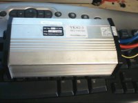
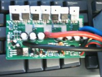
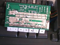
Mkay, build time. Here we have the controller:

Picture 15.jpg

Picture 18.jpg

Picture 17.jpg

It has three Schottkys and four FETS, labeled K3435B. I don't need to upgrade or remove the diodes, do I? The purpose of the diodes in the first place is to send current from the motor back out to the motor, thus "freewheel diodes", correct? How will they be used in this regen config?

Since there are four FETs, and I have 6 4110s on hand, I have a few options to arrange this. Because of PWM multiplication, they should see something like up to 3x the controller current limit. Since they're each rated at >180A, one for each phase should be sufficient, correct?

So, before I do anything, let's make sure my wiring is right. The middle leg of each of these FETs is connected to the motor negative. Left looks like the gate - the conductor is relatively tiny. Right goes through the shunt and to the common positive wire. So the bus I want to cut is the motor negative one, and attach phase wires to that (cut) bus?

Then the common positive and battery negative go to the battery positive and negative respectively. And that's all?
 
The freewheel diodes should just be removed completely. That function will be handled by the body diodes in the main controller.

The FET bus that goes to the motor - is the one that gets chopped up into 3 parts for the phases.
The FET bus that goes to the shunt stays intact, unless we figure out a way to get the shunt in the current path so it can function. Still thinking about that one.

Only part of the current will be going through the braking FETs, part of it will circulate through the main controller. I'm not really sure how big the FETs need to be. To be sure, pairs of 4110's will handle it, but I suspect singles will be fine.

Below is a simplified schematic layout of a typical brushed controller. This might help figure things out.
 
You could install freewheel diodes for each phase. If you did this, some current may be circulated by them, but they will be in parallel with the ones in the main controller.

At any given time, one phase wire will be connected to ground by the main controller.

If the shunt was removed, and effectively relocated to a position between the batteries and both controllers, it could work to limit the regen current. You might be able to use the existing negative controller wire as the shunt.

It would also be cool to reverse the LVC circuit so it becomes a HVC. With the right cutoff setting, the braking controller would cutout if the battery voltage got too high during regen.
 
That sounds well and dandy, but I generally don't understand the operation of these controllers as thoroughly. I'd love a current limit and HVC, but I just don't know now to implement such.

I chopped off the diodes. I've removed the FETs and their legs, but now I can't seem to get the holes clear enough. Maybe 1 in 3 are ready to accept a FET leg. I'll get there, though. I'm afraid that my soldering gun's tip isn't getting hot enough. I'll try replacing that and keep plugging away.

I sent my controller back to Bob Mcree to have it repaired. I have about a week until I have a usable bike to run this on (and rewire my batteries, and install torque arms), so I have some time.

What's the word on that resistor? Should I replace it?
 
You might try the "heat and beat" method to clear the holes. Stick the iron tip into the hole with a dab of fresh solder to heat it up, then quickly whack the board against the table to knock the solder out of the hole.

If you want to power the PWM part off the main battery, you should replace the resistor.
What voltage are you going to run it off?

The current limit might be not too hard to implement. I'll try and make a drawing of the setup. It might be possible to use the shunt in the main controller also.
 
84v now, perhaps as much as 112v later. I could always run that off a tap, though, right?

If you can figure out the current limit, I'll gladly test it out... when I can.

In case we didn't discuss it, or in case I forgot, what would be the result of hitting the brake throttle with the main throttle open? A very fried main controller, correct?
 
lazarus2405 said:
In case we didn't discuss it, or in case I forgot, what would be the result of hitting the brake throttle with the main throttle open? A very fried main controller, correct?

I think it would fry both controllers. It would be ugly. Fuses in the phase wires might help, but no guarantee.

I'll have to sift the archives to find out what value of resistor to use. Frankg did this mod somewhere.
 
That mod I linked used a 2k 5w to drop it on a 60v-72v setup. The one in my unit is a 380.

Three 4110s installed. Now to cut the bus. A cut between each, both sides of the PCB. Think I can just cut the board all the way through? It might be a bit easier for someone lacking a dremil.

Also, on a completely unrelated note, can I connect the reverse/forward key in series with the power button on the analog clyte controllers, for an extra measure of tamper resistance? I've been running with the silly reverse disconnected, and I figured that might be a better use of a key switch.
 
Back
Top