Measuring A123 internal battery resistance again (=10mohm)

avandalen

100 W
Joined
Oct 2, 2010
Messages
177
Location
Maastricht, The Netherlands
Here is the old topic which is locked:

http://endless-sphere.com/forums/viewtopic.php?f=14&t=32211

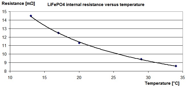
I measured the A123 ANR26650 LiFePO4 internal resistance again. When I take the temperature and the solder tabs into account, the internal resistance is 10mΩ which is equal to the value in the ANR26650 datasheet.
The LiFePO4 battery internal resistance is temperature dependent.

LiFePO4-internal-resistance-versus-temperature.jpg


Website:
http://www.avdweb.nl/solar-bike/batteries.html
 
avandalen said:
The LiFePO4 battery internal resistance is temperature dependent.


Just like every lithium battery...

This is why folks heat race packs before a race.
 
Kind of ironic, its like the drag-race crew with their CO2 extinguishers trying to chill their intercoolers.

I found my digital-camera batteries drained rapidly when I took the camera outside to shoot pictures in the snow and ice of last winter. Is that related?

Sorry the last thread got locked. :(
 
Good info and well done for doing the measurements with your own test setup and calculating everything yourself. I was just trying to make the point that the green A123 26650 cells that are available do generally perform to spec and that there could be some reasons why they fell short in your initial tests. Further tests seem to suggest that was the case, so all good.

I'd better get out of here now before anybody starts a keyboard war against me :)
 
Did a discharge test tonight on an A123 18650, from ebay, got 950mah from a single cell at 5.0A discharge with an accucell 8.

The cell was holding steady at over 3.03v when it was doing this, but the Accucel said something like 2.8v...do I need to do a calibration.

Cell got pretty warm towards the end. Not hot. Just warm.
 
The Mighty Volt said:
Did a discharge test tonight on an A123 18650, from ebay, got 950mah from a single cell at 5.0A discharge with an accucell 8.

The cell was holding steady at over 3.03v when it was doing this, but the Accucel said something like 2.8v...do I need to do a calibration.

Cell got pretty warm towards the end. Not hot. Just warm.


You can NOT test a cell without a 4-wire measurement system. Your data is entirely worthless if you're not using a proper kelvin measurement system.

You need to hook up the balance taps for cell #1 right to the end of the cell itself, then connect your charger charge/discharge leads touching the same end, but not the balance tap leads, and then you can begin to test. If the charger doesn't have the ability to ignore the charge/discharge leads voltage and only use the balance taps, then your charger is not capable of doing cell testing.
 
liveforphysics said:
The Mighty Volt said:
Did a discharge test tonight on an A123 18650, from ebay, got 950mah from a single cell at 5.0A discharge with an accucell 8.

The cell was holding steady at over 3.03v when it was doing this, but the Accucel said something like 2.8v...do I need to do a calibration.

Cell got pretty warm towards the end. Not hot. Just warm.


You can NOT test a cell without a 4-wire measurement system. Your data is entirely worthless if you're not using a proper kelvin measurement system.

You need to hook up the balance taps for cell #1 right to the end of the cell itself, then connect your charger charge/discharge leads touching the same end, but not the balance tap leads, and then you can begin to test. If the charger doesn't have the ability to ignore the charge/discharge leads voltage and only use the balance taps, then your charger is not capable of doing cell testing.

Hi there, thanks for your post, I had never heard of "Kelvin 4 Wire Test".....the only balance taps I have right now are 4s and 8s......I was just testing an individual cell which, ostensibly permitted itself to be discharged at 5Amps.

Charger in question is an 8-150 Turnigy

Thanks.
 
Gotta snip the wires (both) for cell #1. Both of them.

Put them on the cell like I described. See if the charger ignores charge lead voltage and only looks at balance tap voltage. Then you can begin your first worthwhile cell test.
 
liveforphysics said:
Gotta snip the wires (both) for cell #1. Both of them.

Put them on the cell like I described. See if the charger ignores charge lead voltage and only looks at balance tap voltage. Then you can begin your first worthwhile cell test.

sorry to be a pain, but I don't quite follow. I was only testing one cell, how do I get balance taps onto that?

I did do a test with an 8s1p string, which had charge leads and an 8s cellog balance tap.

For some reason, that string, which produced 15A easily during a test with a 24v hub-motor, discharged itselfl in a very regulated fashion at exactly 0.9A when the balance-tap was plugged into the charger, despite my having selected a 5A discharge. Each cell was discharged in turn, remaining balanced all the way.

Sorry to be so slow on the uptake.

thanks again.
 
The Mighty Volt said:
liveforphysics said:
Gotta snip the wires (both) for cell #1. Both of them.

Put them on the cell like I described. See if the charger ignores charge lead voltage and only looks at balance tap voltage. Then you can begin your first worthwhile cell test.

sorry to be a pain, but I don't quite follow. I was only testing one cell, how do I get balance taps onto that?

I did do a test with an 8s1p string, which had charge leads and an 8s cellog balance tap.

For some reason, that string, which produced 15A easily during a test with a 24v hub-motor, discharged itselfl in a very regulated fashion at exactly 0.9A when the balance-tap was plugged into the charger, despite my having selected a 5A discharge. Each cell was discharged in turn, remaining balanced all the way.

Sorry to be so slow on the uptake.

thanks again.

Your charger/discharger is likely limited to a very small discharge wattage. You might be able to discharge a single 3.3V cell at a reasonable current, ie. 5A, but an 8S string can only be discharged at a much lower current to stay within the watt limit for the discharge which is likely around 15W or so.

The Mighty Volt said:
liveforphysics said:
The Mighty Volt said:
Did a discharge test tonight on an A123 18650, from ebay, got 950mah from a single cell at 5.0A discharge with an accucell 8.

The cell was holding steady at over 3.03v when it was doing this, but the Accucel said something like 2.8v...do I need to do a calibration.

Cell got pretty warm towards the end. Not hot. Just warm.


You can NOT test a cell without a 4-wire measurement system. Your data is entirely worthless if you're not using a proper kelvin measurement system.

You need to hook up the balance taps for cell #1 right to the end of the cell itself, then connect your charger charge/discharge leads touching the same end, but not the balance tap leads, and then you can begin to test. If the charger doesn't have the ability to ignore the charge/discharge leads voltage and only use the balance taps, then your charger is not capable of doing cell testing.

Hi there, thanks for your post, I had never heard of "Kelvin 4 Wire Test".....the only balance taps I have right now are 4s and 8s......I was just testing an individual cell which, ostensibly permitted itself to be discharged at 5Amps.

Charger in question is an 8-150 Turnigy

Thanks.

You cannot get accurate voltage values unless you have an additional 2 wires that only measure the voltage, ie a 4 wire kelvin setup. Whilst measuring the capacity in the way you have done is not correct, the actual capacity values produced are probably pretty close to the truth as you are measuring LiFePO4/A123 cells which have a flat discharge curve followed by a very steep curve on the last 5% or so of the discharge. You are monitoring the voltage at the charger which is in fact the voltage of the loaded cell, minus the contact resistance of whatever method you used to connect to the cell * 2, minus the losses in the leads. You need to monitor the voltage with leads that are non current carrying.
 
Cheers Cell_Man. That all makes solid sense. Thanks for clearing up that up, especially the 8s one.

What I was doing was letting the charger/discharger do it thing, then use the fluke multimeter to watch the voltage under stress. Fluke meter reports initial 3.03v under 5C discharge of 1s cell

Doing this, I observed what you mentioned....around the 800mAh+ point of a 5C discharge for an individual cell, the voltage does that "falling-off-the-cliff" trick. Just peels away.

I understood what LFP was talking about after I did a google of the Kelvin 4-wire system, what I didn't understand was how to effect the Kelvin system using just one battery and the materials at my disposal.

I don't think the Turnigy 150w caters for 1s.
 
The Mighty Volt said:
I understood what LFP was talking about after I did a google of the Kelvin 4-wire system, what I didn't understand was how to effect the Kelvin system using just one battery and the materials at my disposal.

I don't think the Turnigy 150w caters for 1s.

If the charger has a balance plug then it's already a kelvin system, which is what Luke was getting at. You just need to work out the pinouts for balance plug, connect the cable and fit the balance wires to the cell or cells under test, then you have your Kelvin system. Without the voltage signal from the balance port it will default to the voltage measured at the charger.
 
cell_man said:
The Mighty Volt said:
I understood what LFP was talking about after I did a google of the Kelvin 4-wire system, what I didn't understand was how to effect the Kelvin system using just one battery and the materials at my disposal.

I don't think the Turnigy 150w caters for 1s.

If the charger has a balance plug then it's already a kelvin system, which is what Luke was getting at. You just need to work out the pinouts for balance plug, connect the cable and fit the balance wires to the cell or cells under test, then you have your Kelvin system. Without the voltage signal from the balance port it will default to the voltage measured at the charger.

Ah I see, he meant I need to figure out what negative balance went to the negative terminal, snip the others, and make sure the soldering of the balance tap {+ and -} stayed out of contact with the charge leads {+ and -} ?? Do I have it now??

Cheers.
 
The Mighty Volt said:
cell_man said:
The Mighty Volt said:
I understood what LFP was talking about after I did a google of the Kelvin 4-wire system, what I didn't understand was how to effect the Kelvin system using just one battery and the materials at my disposal.

I don't think the Turnigy 150w caters for 1s.

If the charger has a balance plug then it's already a kelvin system, which is what Luke was getting at. You just need to work out the pinouts for balance plug, connect the cable and fit the balance wires to the cell or cells under test, then you have your Kelvin system. Without the voltage signal from the balance port it will default to the voltage measured at the charger.

Ah I see, he meant I need to figure out what negative balance went to the negative terminal, snip the others, and make sure the soldering of the balance tap {+ and -} stayed out of contact with the charge leads {+ and -} ?? Do I have it now??

Cheers.


No not really. Just look at any battery pack with balance leads. There will be a negative to the pack negative, then a balance wire that goes on the positive of each cell in the series string. Connect negative balance wire and the first balance wire to the cell while doing your tests. Balance wires are only measurements so you shouldn't do any harm by connecting them wrong, it will just produce an error.
 
Thanks Cell_Man. I have it now. Finally.

Just as a matter of interest.....using just the + and - charge leads, what inaccuracies would present themselves, specifically in the area of a} overall capacity and b} overall discharge rate/capability.

Obviously, the sag under load values are completely screwy and unreliable.

In the meantime, and in related matters, news just in from some of our trusted and friendly eBay retailers of A123 18650's

SzOhMyGOD: "For the cells, we never sell the 5C cells, we know the cells cannot compare with the original A123 30C, but we sell those cells are all tested."


Cammy_CC:"Yes, our battery is the genuine A123.
Each single battery is 2c discharge.
We don't have the black mark under the heat-shrink.
Looking forward for your reply."


Ah yes, the revolutionary and much-coveted 2C A123 cell
free-random-smileys-267.gif
old.gif
 
cell_man said:
No not really. Just look at any battery pack with balance leads. There will be a negative to the pack negative, then a balance wire that goes on the positive of each cell in the series string. Connect negative balance wire and the first balance wire to the cell while doing your tests. Balance wires are only measurements so you shouldn't do any harm by connecting them wrong, it will just produce an error.

Hi, just been re-reading that paragraph...for me, I have a red wire on the pack/string positive, and then a black wire which goes to the negative terminal of that cell.

Each other wire goes to the negative of the next cell in turn, before the final black wire finishes on the negative terminal of the cell which hosts the pack negative terminal.
 
Back
Top