MK1 Honda Insight Power Project

peterperkins

100 W
Joined
Jun 6, 2008
Messages
196
Dear members I have started this thread to allow some ideas to be floated in relation to increasing the power output from the Honda Insight Mk1 IMA system. This may also help with those wishing to use the components in some other EV related application.

I know there are quite a few interested parties and not everyone posts on every forum.

So to start the ball rolling I'm posting a couple of links to relevant threads on www.insightcentral.net where some of the issues have been discussed. It's good background reading.

http://www.insightcentral.net/forums/modifications-technical-issues/16206-inside-mdm-more-power.html

http://www.insightcentral.net/forums/modifications-technical-issues/17481-bcm-gauge-battery-data-display.html

http://www.insightcentral.net/forums/modifications-technical-issues/15146-honda-insight-gen-i-resource-library.html

But replies can be posted here of course 8)

I've recently managed to fake a lower system voltage on the insight motor controller (MCM) which lead to an increase in amps as the system tried to compensate for the perceived lower battery voltage. This rise in amps coupled with the actual battery voltage being 20V higher gave an increase in IMA assist.

During recent testing i have been seeing 93A in 2nd gear WOT battery actual voltage around 160v (Faked to 140v) at that current with batteries warm, so V x A = 14.8kw that's quite a bit better than the 65-70A I was getting before with a high battery voltage. Certainly feels more lively. Added around 3-4kw roughly and probably safe for the motor at that level.

I look forward to other ideas and contributions. Liveforphysics and i have been chatting via PM and the current sensors may be the next target but there are three phase sensors and two other current sensors that probably require hacking/in order to make anything work. Peter
 
I hacked 1 current sensor so far. Going to do some tests on it tonight at work to make sure it behaves as expected.
 
Ok. Here is the characterization of an unmodded factory Insight current sensor:

I'm way past my bedtime. This is all just empirical data, so if you want to graph this to find the trend line and slope or function or whatever, that would be great.

0amps = 2.70v
12amps = 2.80v -12amps = 2.57v
60amps = 3.21v -60amps = 2.17v
90amps = 3.48v -90amps = 1.92v
120amps= 3.76v -120amps = 1.65v
150amps= 4.01v -150amps = 1.42v
180amps= 4.24v -180amps = 1.20v

hall1s.jpg


hall3.jpg


hall2b.jpg
 
Keep going luke. :) How do you propose to modify the voltage output?

The phase sensors will have to have an instant response so i think that precludes a digital modification like ADC> PIc> DAC.

Some sort of analog gizmo.

So lets assume we have a nominal 2.5v zero Amp point, I think that's what the advanced diagnostics says. And to keep it simple lets assume even voltages

So when amps swing to 50A regen we get say 3.00V and when it swings to 50A assist we get 2.00V . A 0.5v shift from the nominal 2.5v null point. Now what we want is to reduce that shift either positive or negative to say 0.4V at 50A a 20% decrease in perceived current at the controller which compensates by allowing more current giving us our increase in power :)

How to do it? Op amp with gain of 0.8?

Now i know a lot of other gurus will be watching this so ideas please. Thanks

Peter
 
From Mike Dabroswki on the IC thread.

Peter,
The easiest way to fake out the current sensors may be to add a current shunt around the sensor, so only 80% of the current passes through the sensor, and 20% flows through the parallel conductor. Getting the ratio right for exactly 80-20 , could be done by setting the stock conductor (copper strip) and current sensor on a bench, and pass a measured current through it, and recording the reading.
Put a second smaller conductor in parallel with the end points, and see how much the current sensor output changes.
You can probably use ring terminals and heavy wire from the bus bar endpoints to a copper strip that you file for calibration.
File the external bus bar until you see exactly 80%.
Want to go back, just remove the external shunt/wire.
Do the same for each sensor that you want to fake.

The battery current sensor that I tap for MIMA is a current loop output type of current sensor.
The zero amps point for the sensor is chassis ground, and it swings positive and negative.
I explained the circuit as you may remember :
http://99mpg.com/blog/batterypacksexpose/batterycurrentsens/
To fake out this type of sensor, a simple resistor to chassis ground will divert some of the current loop signal to ground external to the BCM sense resistor, which is where the current loop signal is changed into a voltage and read by the BCM.
If any of the other current sensors are of the same type, that would be an alternative to the shunt approach.

Interesting stuff.
 
peterperkins said:
Keep going luke. :) How do you propose to modify the voltage output?

The phase sensors will have to have an instant response so i think that precludes a digital modification like ADC> PIc> DAC.

Some sort of analog gizmo.

So lets assume we have a nominal 2.5v zero Amp point, I think that's what the advanced diagnostics says. And to keep it simple lets assume even voltages

So when amps swing to 50A regen we get say 3.00V and when it swings to 50A assist we get 2.00V . A 0.5v shift from the nominal 2.5v null point. Now what we want is to reduce that shift either positive or negative to say 0.4V at 50A a 20% decrease in perceived current at the controller which compensates by allowing more current giving us our increase in power :)

How to do it? Op amp with gain of 0.8?

Now i know a lot of other gurus will be watching this so ideas please. Thanks

Peter

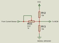
I did it with 3 resistors. The 5v in is regulated. The zero current is always exactly 2. 7v So, a 2 resistor voltage divider to make a 2.7v reference, a resistor in series from the output of the amplified current signal (its not just a hall in the sensor, it has an amp too) going to the center tap of the v-divider, and then its was simply a matter of choosing the right resistor values. I have a 30% decreased output current sensing bi-directionally now. Dont have time to dick with it more tonight though.
 
liveforphysics said:
I did it with 3 resistors. The 5v in is regulated. The zero current is always exactly 2. 7v So, a 2 resistor voltage divider to make a 2.7v reference, a resistor in series from the output of the amplified current signal (its not just a hall in the sensor, it has an amp too) going to the center tap of the v-divider, and then its was simply a matter of choosing the right resistor values. I have a 30% decreased output current sensing bi-directionally now. Dont have time to dick with it more tonight though.

Values?

I sse where your going with the idea we, will have to consider input impedance of MCM input as voltage changes will have to be as fast as with stock system. If we use high value resistors current will be small and may cause problems with MCM input slow response.

Did you get parts numbers for the ic's from inside sensors so we can check specs for max current etc?
 
LMC6494

Its a dip 14 package. (just so you know you found the right datasheet)
 
Something like this then.

CurrentSensorHack.jpg

Lets assume adc input for MCM around 10-20k impedance.
 
Still trying to decide if this is a current or voltage loop system. The MCM current sensor inputs show 10k to ground resistance.
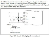
Sounds more like a simple voltage loop. The current sensor has output conditioning components which are almost identical to the example input adc signal conditioning components given in the MCM H8/538 cpu datasheet :? Seems strange they would put them in the sensor rather than at the CPU end? :?H538ADC2.jpg
 
awesome guys
 
peterperkins said:
Still trying to decide if this is a current or voltage loop system.

It's a voltage loop. You can load it with a 10Mohm scope probe, or load it with a 10kohm resistor and it reads the same voltage. The signal output voltage remains virtually identical if you don't pull over 1mA from the sensor output. If you start to load it up, it starts to pull down/up, and about 20-25mA seems to the current limit of the output.


peterperkins said:
Seems strange they would put them in the sensor rather than at the CPU end? :?


Controllers are a very noisey enviroment, it's good to amp the weakest signals (the hall readings) locally. They also only need 5 ECU pins and 9 wires to run the sensors this way, where if you don't combine the bi-directional hall sensor signal output into something that can read them seperately, and combine it into a single 0.2-4.8v signal, then you end up needing 3 extra pins and wires for the ECU harness. It's a good design the way they did it IMO.
 
Live testing.

Interesting I measured the voltage on the 4 MCM current sensor outputs today whilst driving car.

Phase sensors sat exactly at 2.5v and didn't move as far as my multimeter was concerned. Could be becuause it is measuring AC waveform, will try again using AC mode.

Main MCM current sensor voltage went up and down quite readily and V went lower than 2.5V when discharging down to around 1.70v at -70A and above 2.5V and upto 3V around +40A when charging. Fits in with those earlier figures.

I'm going to try and fake main MCM sensor first to see what happens using potential divider and voltage buffer op amp circuit to keep input impedance same. It might be that phase sensors aren't used for current limiting we shall see.

Peter
 
Peter- This wave of phase current is always going to be symmetrical about the 2.5v line. This means the average voltage will always be 2.5v, and a dmm set on DC is always going to read 2.5 regardless of the peak to peak values that the mcu is reading current from.
 
liveforphysics said:
Peter- This wave of phase current is always going to be symmetrical about the 2.5v line. This means the average voltage will always be 2.5v, and a dmm set on DC is always going to read 2.5 regardless of the peak to peak values that the mcu is reading current from.


Agreed i need to scope it just to have a look.
 
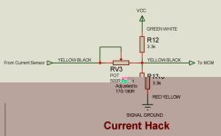
I removed all my voltage hack stuff, ignored the phase sensors and tried a simple PD with a limit resistor on input to PD on the MCM current sensor input. It looks like the below.

I found out several things.

I choose the PD values to bring down the impedance of the circuit to make it less noise suceptible. Tweaking the 500R input pot I found the sweet spot was around 160-170R. This allowed current upto 95amps on the BCM gauge without recourse to any voltage tweaking or faking and with my battery at 155-160v under that load. Around 14.7kw peak. Very nice and a lot simpler than the voltage hack.

Increasing the pot resistance gave more current but above 180R (97A+ on gauge!) after a few seconds the BCM/IMA would hard reset and a P1568 current error would occur. It appears the BCM was producing this error as the soc fell to zero as if system had been re-booted, so I think I ran into the BCM hard current limit of around 100A. That's fair enough and a few issues need to be tackled before i go looking for 100A+ anyway.

With MCM current set to max at 95A no errors occured using circuit below.

So to progress further I need to

1) Change my main fuse to 150A

2) Fake either the BCM interceptor current and or error flag output or the BCM current sensor input to prevent it reaching hard limit and setting code.

If I capture some BCM Gauge raw hex data should be able to see the byte where BCM is setting a code and just use interceptor to null / remove it.

Op amp voltage follower buffer probably good idea so may add that to this hack.
CurrentHack.jpg
 
Changed main power fuse to 150A in preperation for further testing this week :D
 
Cool. :)

I've got before-mod dyno's of my car with and without electric assist.

I'm going to try a few different current percentage increases and make sure torque grows linearly with phase current so we know we aren't stator tooth saturated or something weird we didn't expect.

I can also measure the resistance and inductance of the motor now that I've got a precision LCR meter. :) This will help characterize the motor and see where the potential torque limits would be for a given pack voltage so we don't have to wonder what point's don't make sense to exceed.
 
insightdyno.jpg
 
Nice Luke

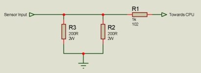
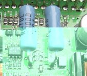
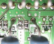
Looking inside the Insight Mk 1 BCM at current sensor input circuitry. We have 2 big 200R resistors in parallel to ground making the current loop. So 100R effective resistance. There is then a little 1k resistor from the input leading off towards cpu area.
Took some pics. hopefully can tweak those to simulate lower current flow.

BCMCurrentInput.jpg

The is no evidence of a similar configurationn in the MCM so as has been postulated earlier the MCM sensors are voltage loop devices and the BCM is a current loop device.

InsideBCM 001.jpg
InsideBCM 004.jpg
 
Going to try this today!!


Seems fine at the moment :) Not giving me anything much above 100A yet but is not giving the BCM/MCM current mismatch errors it was before which is progress. Still learning. Descending long steep hill near home and managed consistent 62A regen until BCM did it's normal slow cutback after about 20-30 seconds.

Of course may reach a point soon when back emf etc and other resistances will just not allow a higher current with the battery voltage I have available under load. This may be where a higher pack voltage comes in. My cells are sagging to 150v under 100A load when less than 20C. Time for those nice nano poly cells!!! and a plug in board which can go upto 200+V LOL

Be interesting to see if the rally car with two more cells gives more current with the same mods.

Pics of the BCM current hack inside the bcm. Shows the 500R pot adjusted so the Current sensor is now 75R instead of 100R. Now I may need to change this for a nice fixed higher wattage prescion 300R resistor to get the consistent OEM accuracy. But it works for now and is adjustable. Just 4 screws to take top off and adjust.

I still have to assemble the MCM opamp part of the hack on some stripboard and move that into the MCM box so it is screenend from the noise etc. I think that is picking up a bit of noise where it is at the minute. Again I will place the pot for that just under lid so you can whip off the lid and adjust it.

All good fun.
 
This stuff is way over my head. These guys seem to have figured out what you are trying to do.
http://99mpg.com/mima/mimaintroduction/
They seem to be focused on efficiency rather than power .
Hope this is of some help.
Brad
 
Very interersting findings, I ventured into my shed for an hour as luckily my car was in garage before snow came so it's clean and dry but stuck in there. Only -1C today brr!

Anyway I attached my dc power supply to the car with standard BCM/MCM settings. Fed IMA 168v via grid charger connection points with battery off. I turned on ignition (engine off) and no ima errors and all settled down normally.

Cranking up the voltage slowly I reached about 225v before IMA light came on. As I was slowly increasing the voltage I had noticed BCM gauge increased to 214v and then stuck, so it appears BCM is only able to report voltages upto 214V back to MCM. As I continued increasing voltage upto and above 225V the voltage difference check between MCM detecting 225v+ & BCM stuck at 214V came into play and triggered the P1576 code. That's actually not a problem as this was without the voltage hacks, and with the BCM fooler voltage hack the BCM/MCM will only see "Normal voltages" so the 214v limit is irrelevant but just interesting.

I reset the codes and forced the DC-DC converter to come on by cutting the black/green inhibit wire and tried again. The converter operated normally until around 224V then it tripped off until voltage was turned down a bit again. No IMA error at this point. So looks like limit for DC-DC input voltage is around 222V, which will limit the battery voltage increases to an absolute max of around 220v if we want the converter to operate at all times and all battery voltages. Of course if we are not bothered about the DC-DC converter working until the battery falls to normal operating voltage rather than peak charge voltage then we may be able to go a bit higher than 220V. For now I will aim for 220V abs max system voltage.

Interestingly I never got an over 192V error, this may be because engine was not running and could possibly be linked to active regen. Again with the voltage hacks in place the MCM will ony see normal voltages anyway so this should not be an issue.
 
I've now upped the sytem voltage to 200V resting, 220V fully charged.

No voltage errors but a couple of other errors due to my tinkering :roll: As i've been hacking the wiring about with all the breadboard work I suspect a broken connection.

Hope to test in earnest next week.
 
Great work Peter!

Inductively, there is going to be some jumping and bouncing going on, so if it shuts down at ~220v, I wouldn't exceed 200v as peak battery voltage, and even then, you're going to want to add quite a bit of well-placed extra cap to try to keep it from jumping past 220v.


If you go with 45-90c Nano-techs, I can confirm the 4Ah cells can handle 300amps continuously from start to finish, and they stay cool(luke warm) for the top ~65% of discharge, but the temp does start to rapidly climb as SOC drops and Ri increase during the bottom of the SOC area, so if at all possible, I would stick with only using the top half of the SOC if you're planning to be pushing them to the limits.
 
Back
Top