Mr. Mik
1 kW
- Joined
- Sep 3, 2008
- Messages
- 390
There will be some updates and edits to the post in this thread as needed, so that the main content of the thread remains concentrated at the beginning.
Hopefully it will get better over time!
Here is a bit of an "Index" for the posts following further down:
External links to sites with information about the identical Honda Insight and Civic "Sticks":
http://www.99mpg.com/blog/batterypacksexpose/
http://www.insightcentral.net/forums/modifications-technical-issues/16517-what-actually-goes-wrong-batteries.html
http://www.insightcentral.net/forums/modifications-technical-issues/
.
Replacement battery modules are available from (incomplete list): https://www.endless-sphere.com/forums/viewtopic.php?f=14&t=12764&p=405325#p405325
.
Anatomy of a single stick and the temperature sensor strip: https://www.endless-sphere.com/forums/viewtopic.php?f=14&t=12764#p189794
and https://www.endless-sphere.com/forums/viewtopic.php?f=14&t=12764&start=15#p236082
Pictures of the Battery-ECU https://www.endless-sphere.com/forums/viewtopic.php?f=14&t=12764#p189796
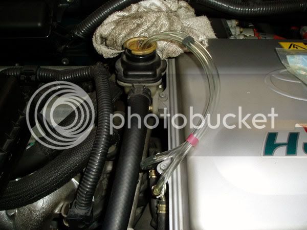
Changing the inverter coolant: https://www.endless-sphere.com/forums/viewtopic.php?f=14&t=12764&p=189796#p211972
Getting it into diagnostic mode: https://www.endless-sphere.com/forums/viewtopic.php?f=14&t=12764#p211973
Error codes: https://www.endless-sphere.com/forums/viewtopic.php?f=14&t=12764&p=293008#p293008
S2000 scanner menu mindmap: http://endless-sphere.com/forums/viewtopic.php?f=14&t=12764&start=60#p346399
Suggested service summary: https://www.endless-sphere.com/forums/viewtopic.php?f=14&t=12764#p211974
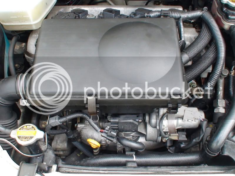
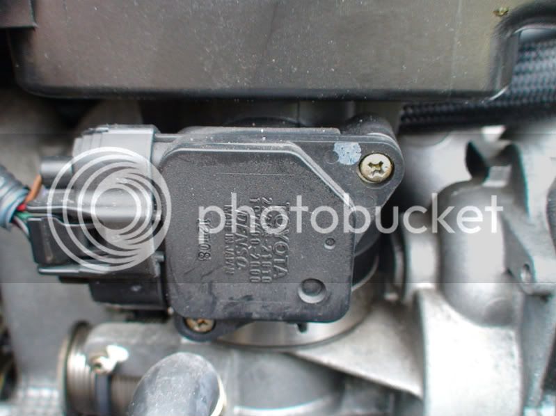
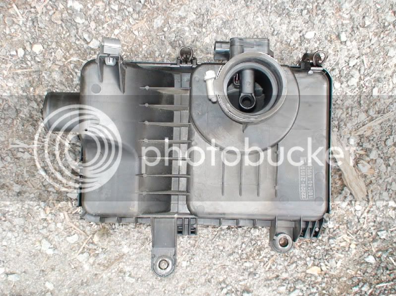
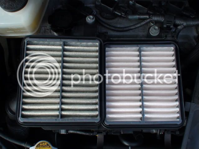
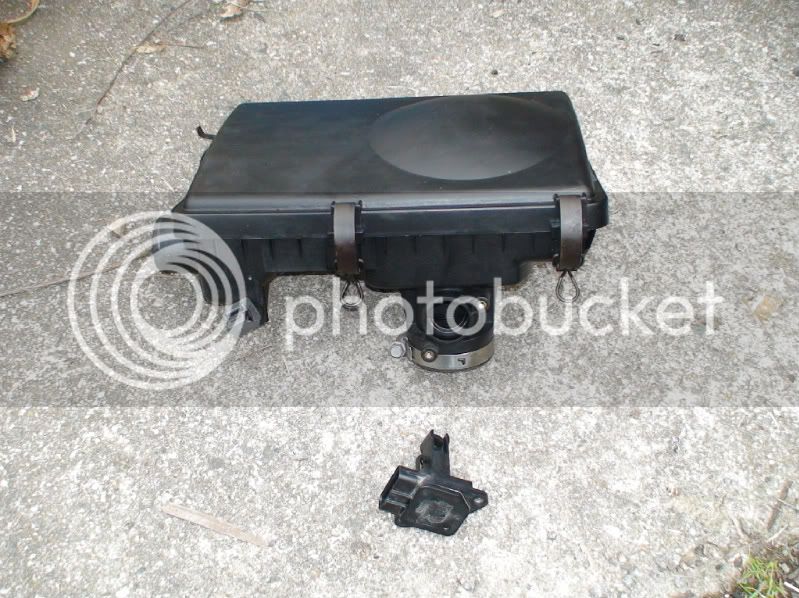
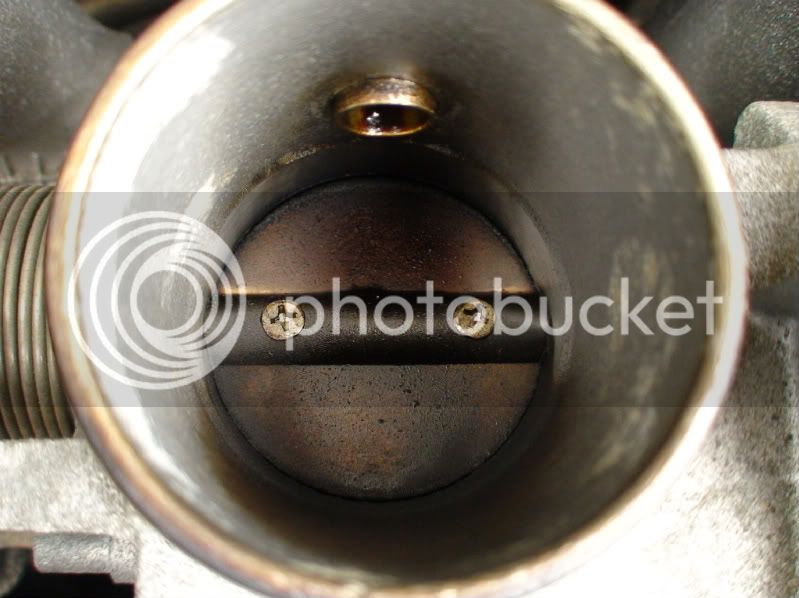
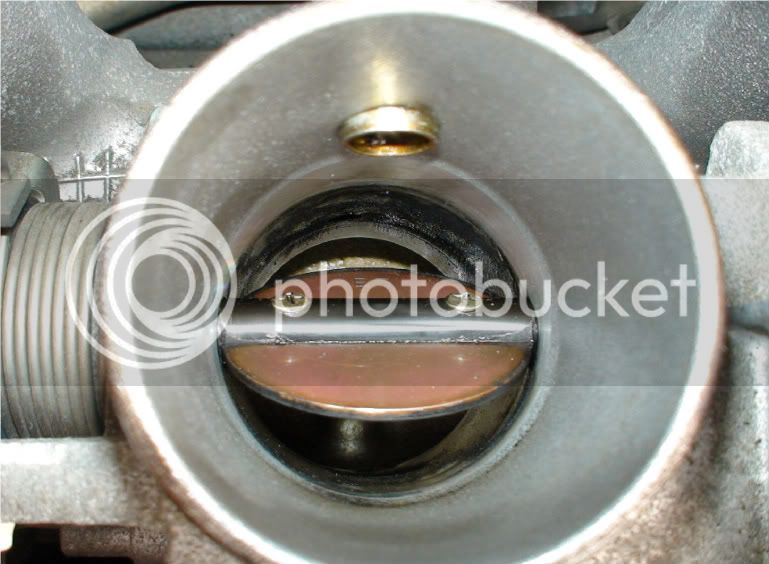
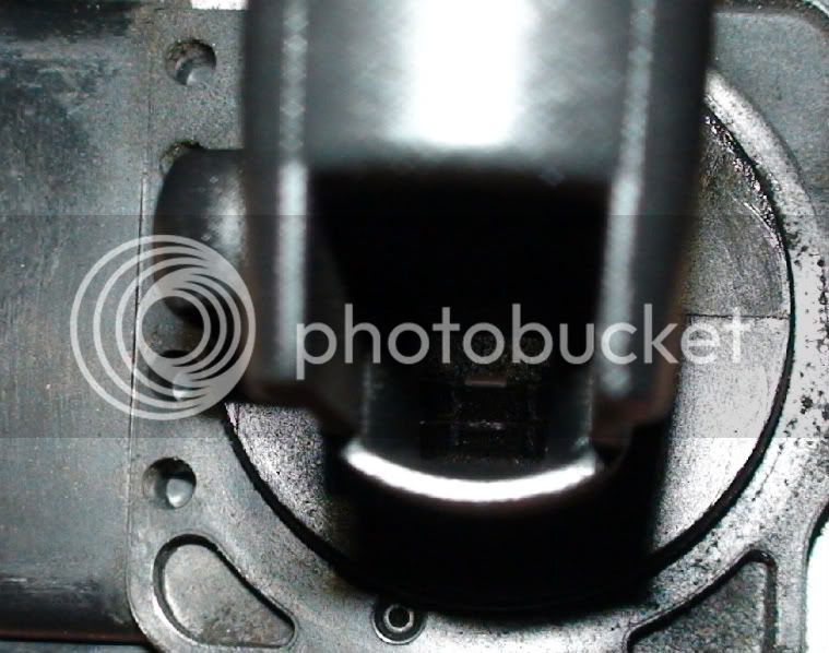
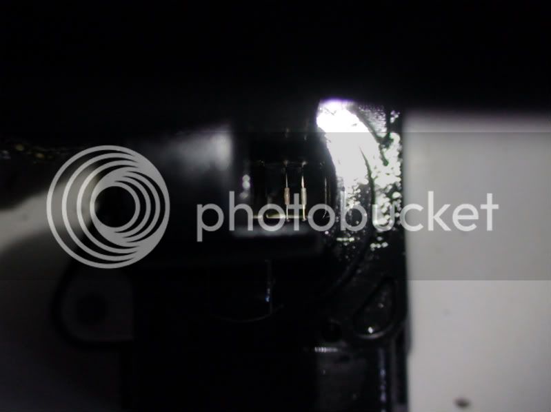
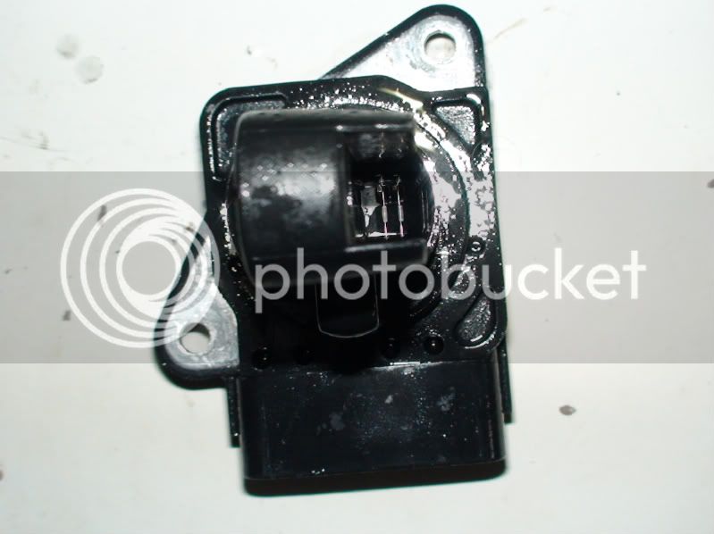
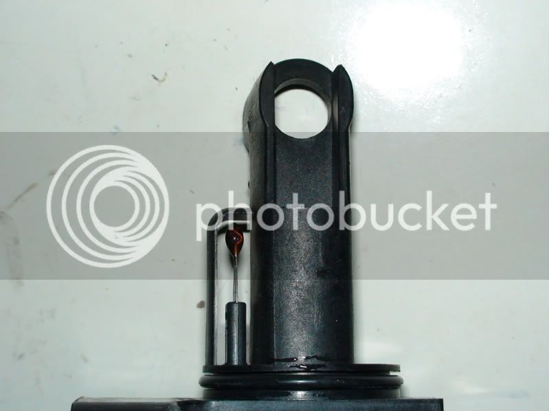
The MAF Sensor and how to clean it: https://www.endless-sphere.com/forums/viewtopic.php?f=14&t=12764#p211975
Results of 3-weeks self-DC test and how to detect a single cell hitting zero V during discharge: https://www.endless-sphere.com/forums/viewtopic.php?f=14&t=12764&start=15#p252369
.........................................................................................................................
An experimental NHW10 EQ charger design: Special Freddy 8.0 https://www.endless-sphere.com/forums/viewtopic.php?f=14&t=12764&p=272207#p272207
And a later version of the Special Freddy NHW10 EQ charger V10.9: https://www.endless-sphere.com/forums/viewtopic.php?f=14&t=12764&p=284578#p284578
And the so far latest version of Special Freddy NHW10 EQ charger V15.3: https://www.endless-sphere.com/forums/viewtopic.php?f=14&t=12764&p=396167#p396167
.........................................................................................................................
The Panasonic Patent on how to replace faulty cells in batteries: https://www.endless-sphere.com/forums/viewtopic.php?f=14&t=12764&p=278386#p278386
Mr. Mik's way of finding the worst capacity cell in a battery: https://www.endless-sphere.com/forums/viewtopic.php?f=14&t=12764&start=45#p279315
The DiPoD: A device to tell if you are burning Dino Poop: https://www.endless-sphere.com/forums/viewtopic.php?f=14&t=12764&p=278622#p278622
My latest "best" method to test a NHW10 battery for faulty sticks: https://www.endless-sphere.com/forums/viewtopic.php?f=14&t=12764&start=45#p287068 (unless I came up with something better and did not change this link, yet....always working on improvements!)
.
..........
.........
.
These batteries are also known as Prius Mk1 or NHW10 traction battery (made by Panasonic).
The Prius Mk1 were apparently only sold in Japan, but are more recently being exported as used cars to other countries.
They are often in good shape, but their weak point is the about 10 year old battery pack.
The NHW10 battery is a 240s NiMH battery consisting of 2 half-packs (HP's) with 20 "sticks" in each of them.
Each stick is made of 6 "D"-sized NiMH cells in serial connection.
The D-cells are firmly welded together to make up a "Stick"and have a female screw connector at each end.


The sticks are therefore 7.2V NiMH batteries and they have a nominal capacity of 6.5Ah.
Dimensions:
35mm diameter (at the widest parts)
381mm length (+ screw and connector and temp sensor strip)
400mm total length (approximately, with screws, connectors, BMS tabs, temp sensors etc etc etc)
The form factor is quite different from the better known NHW11 and NHW20 (prismatic) cells from the later Prius models.
These sticks might be far superior to the newer prismatic cells in some applications, particularly because they do not require compression.
The screw connector at each end makes it relatively easy to assemble them into serial or parallel battery packs with very high discharge current capability, voltages and capacity.
There are of course many uses for these batteries other than keeping Prius Mk1 hybrids going for longer.
But selling some sticks to help owners to keep the first hybrids running longer can't be all bad, either!
For applications other than the replacement of defective modules in Prius Mk1 batteries, I suggest to use the following parameters. Sticking to similar parameters is the reason for the phenomenal longevity of the NiMH cells in Toyota Prius and Toyota RAV4-EV cars!
Keep the SOC between 80% and 20% for the vast majority of the batteries life span. Occasional full charges and deep discharges are useful for equalizing and reconditioning, but the longevity of these cells will suffer if they are regularly cycled from full to empty.
Keep them cool whenever possible. They function best at similar ambient temperatures to our human comfort zone: Around 24degrees Celsius!
Use forced air cooling if the battery temperature tends to get high during operation. These batteries can produce very high currents and they can also absorb high currents during regenerative braking, but they need either much time to cool down or active cooling if such high currents are required frequently.
These are the steps before the actual testing can begin:
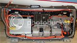
1) Dis-assembly of the Prius battery pack, so that the dangerous 288V serial connection is reduced to 40 x 7.2V. From then on the modules will be much safer to handle. If you are competent and confident with high voltage DC, it is much faster to cycle an entire pack or two half-packs than to cycle individual sticks. But this is much more dangerous and needs special equipment and safety measures.
2) The modules are then individually removed from the battery, cleaned and inspected for any external damage.
3) Any cracks in the shrink-wrap tubing which covers the modules are repaired with shrink-wrap to prevent accidental shorting between sticks.
4) Both module terminals are then polished to ensure a low resistance electrical connection.
5) The terminals for the temperature sensor strip are then covered with shrink-wrap. This prevents accidental shorting of the module through it's temperature sensors.
After that, the sticks are ready for the testing program. What I have come up with over a month or so of experimenting with these cells is this testing program:
(This keeps changing, of course, hopefully getting better in the process...)
.
EDIT: The below procedure is too time consuming. I now prefer to charge a half-pack or entire pack and then let it self-discharge for several weeks. Unfortunately this is much more dangerous because the HP remains potentially lethal for the entire resting and testing time.
.
Systematic Testing Series 1:
Charge
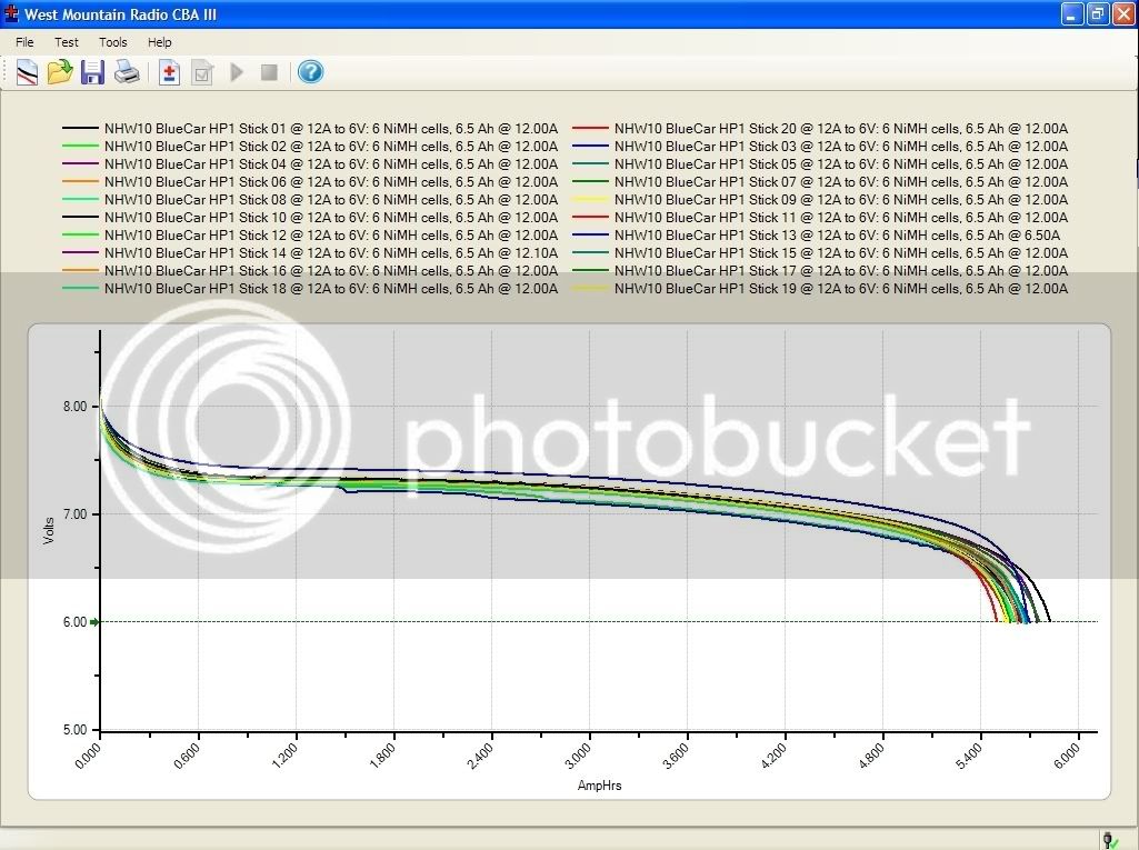
CBA2 Capacity test at 6.5A to 6.6V Nr1
CBA2 Capacity test at 0.7A to 5.4V Nr1
Charge
CBA2 Capacity test 17A for 1Ah directly after charging
Check Voltage at 1Ah end point.
CBA2 Capacity test at 11.95A to 5.4V directly after 17A test.
CBA2 Capacity test at 0.65A to 5.4V Nr2
Charge
100A test; 10seconds (that is about 0.28Ah capacity drained)
Note: Voltage (V): Before: At 10sec point:
60A discharge test to 6.0V: Time to cutoff voltage (s):
Approximate Ah:
Cell temperatures (DegC): Highest: Lowest:
Charge
CBA2 Capacity test 6.5A to 5.4V Nr2
Charge and wait 2 weeks.
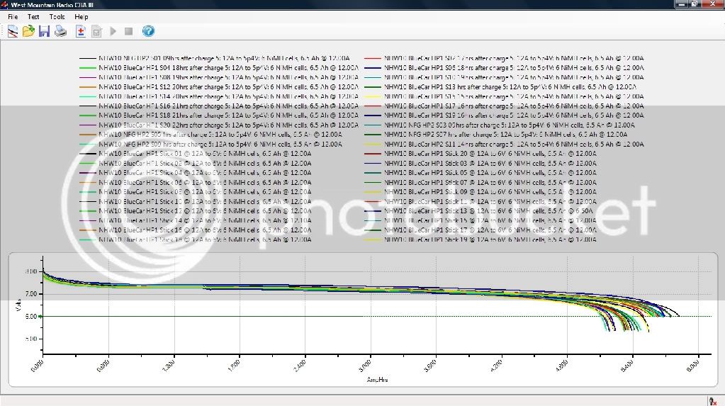
CBA2 Capacity test 6.5A to 5.4V Nr3; Note open Voltage before test (V):
CBA2 Capacity test at 0.65A to 5.4V
Charge to 2.6Ah @ 3A; Note charger end voltage (V):
This testing schedule might seem a little grueling, and it is...
The worst part was the 2 week holiday (absolutely necessary to keep me away from the sticks during the 2 week self discharge waiting time!)
Hopefully it will get better over time!
Here is a bit of an "Index" for the posts following further down:
External links to sites with information about the identical Honda Insight and Civic "Sticks":
http://www.99mpg.com/blog/batterypacksexpose/
http://www.insightcentral.net/forums/modifications-technical-issues/16517-what-actually-goes-wrong-batteries.html
http://www.insightcentral.net/forums/modifications-technical-issues/
.
Replacement battery modules are available from (incomplete list): https://www.endless-sphere.com/forums/viewtopic.php?f=14&t=12764&p=405325#p405325
.
Anatomy of a single stick and the temperature sensor strip: https://www.endless-sphere.com/forums/viewtopic.php?f=14&t=12764#p189794
and https://www.endless-sphere.com/forums/viewtopic.php?f=14&t=12764&start=15#p236082
Pictures of the Battery-ECU https://www.endless-sphere.com/forums/viewtopic.php?f=14&t=12764#p189796
Changing the inverter coolant: https://www.endless-sphere.com/forums/viewtopic.php?f=14&t=12764&p=189796#p211972
Getting it into diagnostic mode: https://www.endless-sphere.com/forums/viewtopic.php?f=14&t=12764#p211973
Error codes: https://www.endless-sphere.com/forums/viewtopic.php?f=14&t=12764&p=293008#p293008
S2000 scanner menu mindmap: http://endless-sphere.com/forums/viewtopic.php?f=14&t=12764&start=60#p346399
Suggested service summary: https://www.endless-sphere.com/forums/viewtopic.php?f=14&t=12764#p211974
The MAF Sensor and how to clean it: https://www.endless-sphere.com/forums/viewtopic.php?f=14&t=12764#p211975
Results of 3-weeks self-DC test and how to detect a single cell hitting zero V during discharge: https://www.endless-sphere.com/forums/viewtopic.php?f=14&t=12764&start=15#p252369
.........................................................................................................................
An experimental NHW10 EQ charger design: Special Freddy 8.0 https://www.endless-sphere.com/forums/viewtopic.php?f=14&t=12764&p=272207#p272207
And a later version of the Special Freddy NHW10 EQ charger V10.9: https://www.endless-sphere.com/forums/viewtopic.php?f=14&t=12764&p=284578#p284578
And the so far latest version of Special Freddy NHW10 EQ charger V15.3: https://www.endless-sphere.com/forums/viewtopic.php?f=14&t=12764&p=396167#p396167
.........................................................................................................................
The Panasonic Patent on how to replace faulty cells in batteries: https://www.endless-sphere.com/forums/viewtopic.php?f=14&t=12764&p=278386#p278386
Mr. Mik's way of finding the worst capacity cell in a battery: https://www.endless-sphere.com/forums/viewtopic.php?f=14&t=12764&start=45#p279315
The DiPoD: A device to tell if you are burning Dino Poop: https://www.endless-sphere.com/forums/viewtopic.php?f=14&t=12764&p=278622#p278622
My latest "best" method to test a NHW10 battery for faulty sticks: https://www.endless-sphere.com/forums/viewtopic.php?f=14&t=12764&start=45#p287068 (unless I came up with something better and did not change this link, yet....always working on improvements!)
.
..........
.........
.
These batteries are also known as Prius Mk1 or NHW10 traction battery (made by Panasonic).
The Prius Mk1 were apparently only sold in Japan, but are more recently being exported as used cars to other countries.
They are often in good shape, but their weak point is the about 10 year old battery pack.
The NHW10 battery is a 240s NiMH battery consisting of 2 half-packs (HP's) with 20 "sticks" in each of them.
Each stick is made of 6 "D"-sized NiMH cells in serial connection.
The D-cells are firmly welded together to make up a "Stick"and have a female screw connector at each end.


The sticks are therefore 7.2V NiMH batteries and they have a nominal capacity of 6.5Ah.
Dimensions:
35mm diameter (at the widest parts)
381mm length (+ screw and connector and temp sensor strip)
400mm total length (approximately, with screws, connectors, BMS tabs, temp sensors etc etc etc)
The form factor is quite different from the better known NHW11 and NHW20 (prismatic) cells from the later Prius models.
These sticks might be far superior to the newer prismatic cells in some applications, particularly because they do not require compression.
The screw connector at each end makes it relatively easy to assemble them into serial or parallel battery packs with very high discharge current capability, voltages and capacity.
There are of course many uses for these batteries other than keeping Prius Mk1 hybrids going for longer.
But selling some sticks to help owners to keep the first hybrids running longer can't be all bad, either!
For applications other than the replacement of defective modules in Prius Mk1 batteries, I suggest to use the following parameters. Sticking to similar parameters is the reason for the phenomenal longevity of the NiMH cells in Toyota Prius and Toyota RAV4-EV cars!
Keep the SOC between 80% and 20% for the vast majority of the batteries life span. Occasional full charges and deep discharges are useful for equalizing and reconditioning, but the longevity of these cells will suffer if they are regularly cycled from full to empty.
Keep them cool whenever possible. They function best at similar ambient temperatures to our human comfort zone: Around 24degrees Celsius!
Use forced air cooling if the battery temperature tends to get high during operation. These batteries can produce very high currents and they can also absorb high currents during regenerative braking, but they need either much time to cool down or active cooling if such high currents are required frequently.
These are the steps before the actual testing can begin:
1) Dis-assembly of the Prius battery pack, so that the dangerous 288V serial connection is reduced to 40 x 7.2V. From then on the modules will be much safer to handle. If you are competent and confident with high voltage DC, it is much faster to cycle an entire pack or two half-packs than to cycle individual sticks. But this is much more dangerous and needs special equipment and safety measures.
2) The modules are then individually removed from the battery, cleaned and inspected for any external damage.
3) Any cracks in the shrink-wrap tubing which covers the modules are repaired with shrink-wrap to prevent accidental shorting between sticks.
4) Both module terminals are then polished to ensure a low resistance electrical connection.
5) The terminals for the temperature sensor strip are then covered with shrink-wrap. This prevents accidental shorting of the module through it's temperature sensors.
After that, the sticks are ready for the testing program. What I have come up with over a month or so of experimenting with these cells is this testing program:
(This keeps changing, of course, hopefully getting better in the process...)
.
EDIT: The below procedure is too time consuming. I now prefer to charge a half-pack or entire pack and then let it self-discharge for several weeks. Unfortunately this is much more dangerous because the HP remains potentially lethal for the entire resting and testing time.
.
Systematic Testing Series 1:
Charge
CBA2 Capacity test at 6.5A to 6.6V Nr1
CBA2 Capacity test at 0.7A to 5.4V Nr1
Charge
CBA2 Capacity test 17A for 1Ah directly after charging
Check Voltage at 1Ah end point.
CBA2 Capacity test at 11.95A to 5.4V directly after 17A test.
CBA2 Capacity test at 0.65A to 5.4V Nr2
Charge
100A test; 10seconds (that is about 0.28Ah capacity drained)
Note: Voltage (V): Before: At 10sec point:
60A discharge test to 6.0V: Time to cutoff voltage (s):
Approximate Ah:
Cell temperatures (DegC): Highest: Lowest:
Charge
CBA2 Capacity test 6.5A to 5.4V Nr2
Charge and wait 2 weeks.
CBA2 Capacity test 6.5A to 5.4V Nr3; Note open Voltage before test (V):
CBA2 Capacity test at 0.65A to 5.4V
Charge to 2.6Ah @ 3A; Note charger end voltage (V):
This testing schedule might seem a little grueling, and it is...
The worst part was the 2 week holiday (absolutely necessary to keep me away from the sticks during the 2 week self discharge waiting time!)
")