Mobility use - 14" wheels and hub motors?

hallkbrdz

100 W
Joined
Mar 24, 2018
Messages
249
Location
Edmond, OK USA
I've starting to work on an open source design for a power chair (powered wheelchair), and one of the many design goals is to have reasonably sized front set of wheels so that it can climb up things like full-sized curbs. To do that you need a wheel more than twice the height of the obstacle with knobby tires. Here in the US curbs are typically 5-6 inches high, so a 14" wheel should generally be acceptable with a high torque wheel hub motor. Max speed here is 5-6 MPH, so a gear reduced motor should be most appropriate. This is just an option for now, as I might use in-board motors instead, but I wanted to pursue this option as well.

Some questions:

1. How easy / hard is to get and then wire in spokes for a short wheel like this? I admit I've never done anything but replace a spoke or two on a bike in my life, or tighten up loose ones, but I assume there is some length in that it becomes more difficult to adapt a hub motor to a spoke wheel?

2. What motors are well thought of and readily available that might be a good fit for this sort of application? 48v or less would be ideal for FAA air travel reasons (sealed LFP battery).

Thanks in advance
 
Last edited:
Something like this?


There are a lot of wheelbarrow tires in that size. Typically they measure about 15" inflated.
 
Thanks for that, but at 80 nm of torque it's too weak. Not that it might do at least double that for a couple seconds, although with the added weight calculations show 180 nm will be required with no momentum.

Since then, and with the goal of keeping it as light as possible, I've found that a larger diameter hub (single sided mount variety) in the 1200-1600W size with a lighter BMX style tire in the 20" size seems doable if it is approached with some momentum (and any of the datasheets are halfway correct). Furthermore, using a "trailing arm" suspension on the front end with an air shock to allow 6" or more of travel seems like it may be the simplest and lightest solution to deal with that sudden shock.

I'm personally taking some inspiration from the Outrider Coyote design. A very well thought out 4WD platform with a larger frame, it's just over 200 lbs. With only FWD, smaller trailing wheels and a compact frame, I think 150 lbs should be possible with smart material selections.
 
What are you trying to design exactly? For what kind of user and what kind of terrain?
A normal wheelchair with an attachable electric handbike would be the simplest solution.

Electric handbike (build it with a 14.5 inch wheelbarrow hub motor)


If you are looking for low speed and high torque hub motors the suggestion from Chalo for wheel barrow motors is a good one.
Here are some single, double and 4WD options:

Single wheel motor

Dual set up

4WD kit
 
Thanks for that, but at 80 nm of torque it's too weak. Not that it might do at least double that for a couple seconds, although with the added weight calculations show 180 nm will be required with no momentum.

For a wheel that can take a 14" OD tire? Not likely.

But 4 such wheels total 320 Nm rated torque.
 
Wheelchair prototype.png.jpg
Here is a rough design mock-up for what I'm working on to arrange the mechanical items (ignore the correctly sized but crude seat and leg supports). Unlike a "normal" wheelchair, the large wheels are placed out front to allow it to climb obstacles that can be encountered in the city like this 6 inch curb. You need a wheel more than twice as tall as the obstacle to climb it.

The reason for using spokes is to save mass on a large diameter wheel. Every amount of mass that can be removed reduces the torque required for the hub motors to climb obstacles. Additionally, using BMX tires makes it simple to get replacements as needed. Since the wheel needs to be large it has to be on the side, and it also needs to be somewhat narrow so that the chair can still easily fit through doorways.

The first goal of the design is to use as much common off-the-shelf hardware as possible so that they are easily and quickly serviceable by just about anyone without any special tools. A big problem with all the vendor powered wheelchairs is that when they break down, the wait time for repair can be weeks to months. That's inexcusable when you are fully dependent on the device to get around, not that insurance companies or the government care.

The second goal is affordability. It does no good to make a spectacular design if nobody can afford it. Because all insurance or Medicare will pay for is what is "medically necessary", generally anything beyond a manual chair is on your own dime. They don't care if you can leave your house, as that isn't necessary in their view. But nobody should be trapped like that because of costs.

Another goal is water resistance. Rainstorms should not cause the chair to fail. That's inexcusable.

Live link to 3D model: Onshape
 
Last edited:
The reason for using spokes is to save mass on a large diameter wheel. Every amount of mass that can be removed reduces the torque required for the hub motors to climb obstacles.

Then understand that every mm of difference between the motor air gap diameter and the wheel diameter reduces the maximum torque you can get from a given width of stator, and that's more important in the equation than wheel mass, by a lot. If torque is the critical value and wheel diameter is fixed, then a motor whose hub shell is also the tire mounting surface is how you maximize torque. That's how dorky little stand-up scooters do it, for good reasons.

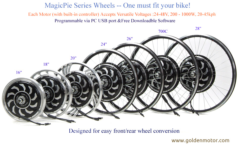
Magic Pie 1 from Golden Motor, which is a direct drive motor, can develop 93 Nm of torque. That's mostly due to its diameter. Motors with gear reduction don't need as much diameter, but it still dictates how much torque they can make.

MagicPie%20Series.jpg


No spokes, tire mounted directly on motor housing, would make it easier to do what you propose. High ratio gear reduction would also help, but only if the gears can withstand the torque you are trying to make.

Powered rear wheels help the front wheels surmount obstacles. That's why some 4WD vehicles can climb steps higher than their front hubs.

 
Here is a rough design mock-up for what I'm working on: View attachment 358238

Great that you are trying to design an affordable and easily repairable powered wheelchair.

Some concerns I have with this design are the independent suspension making it less stable and even easy to fall over if a user would try to climb a curb this way. Avoidable by always climbing obstacles straight on or reducing the independent suspension.
But when you do get the big front wheels on to a sidewalk the center of mass will be tilted backwards. That will reduce the weight and thus grip on the front wheels preventing the small rear caster wheels from being able to be pulled up onto the sidewalk.
 
So I spoke with Thomas and a member of his team today. Their design was much more complete that I they let on publicly.

This first model uses 16 inch bicycle tires (kid bmx) on what I believe is a custom rim. The two front wheels are driven with a double differential that uses a 1KW motor for forward and reverse drive and a smaller motor to send the power left or right to turn and to allow it to spin in place. To make up for the small volume of air in the tires, air bags are used for suspension. The rear caster wheels are on a tilt mechanism that is pushed down with a spring. That should keep all four wheels on the ground at all times. Although the foot rest is too low to clear a large curb, the plan is to raise this when approaching a curb with another motor. I may be involved on the electronics and programming side for things like bluetooth integration, which is not yet complete.

On the upside, I did get to learn a lot about onshape this last week, along with alternate suspension designs and a good review of available motors. I do think a 4 link bell crank design would actually work quite well using two bicycle spring/dampers in addition to (not yet complete) a means to push down on the rear wheel when the same side front wheel is pushed upward, keeping it more level. With some simple custom hardware, a Citroen 2CV style suspension could also be attempted. True, just using airbags is much easier.

My second attempt up until this afternoon: Onshape
 
Yes I'm aware of those motor / gear units. Personally I'd avoid any brushed motor and 90 degree angled drive for this sort use in a new design. They require more maintenance than is necessary using larger direct drive axial 3 phase motors, along with having no regen for outdoor use.

The swincar looks interesting, the tilt aspect of it is certainly novel.

I guess I don't share your concerns over independent front suspension. Even with some weight transfer at least 50% of it should still be on the large wheels due to pushing the rear wheels down, providing more than sufficient traction.
 
Then understand that every mm of difference between the motor air gap diameter and the wheel diameter reduces the maximum torque you can get from a given width of stator, and that's more important in the equation than wheel mass, by a lot. If torque is the critical value and wheel diameter is fixed, then a motor whose hub shell is also the tire mounting surface is how you maximize torque. That's how dorky little stand-up scooters do it, for good reasons.

Magic Pie 1 from Golden Motor, which is a direct drive motor, can develop 93 Nm of torque. That's mostly due to its diameter. Motors with gear reduction don't need as much diameter, but it still dictates how much torque they can make.


No spokes, tire mounted directly on motor housing, would make it easier to do what you propose. High ratio gear reduction would also help, but only if the gears can withstand the torque you are trying to make.

Powered rear wheels help the front wheels surmount obstacles. That's why some 4WD vehicles can climb steps higher than their front hubs.

Yes I understand the issue with tire diameter and torque. Optimally that 20" wheel would be made for 20x4 tires and have an ~18 inch motor, but it's pretty close. Advertised torque is a little less than required, but for short burts it might work.
 
Personally I'd avoid any brushed motor and 90 degree angled drive

The right angle drive is a result of worm gear reduction, which in a power chair application has the benefit of locking the wheels in position when the motor isn't running. That can also be a disadvantage in a dead motor scenario, so most such chairs have disconnectable couplings so that a nonfunctioning one can be pushed.
 
I realize that, but other than for maybe the fold-up ones, there's no reason to do that any longer. It's just lazy old tech on the high-priced chairs. At least use in-line AC motors with a long-lasting planetary gearbox.
 
I realize that, but other than for maybe the fold-up ones, there's no reason to do that any longer. It's just lazy old tech on the high-priced chairs. At least use in-line AC motors with a long-lasting planetary gearbox.
Neither brushless motors nor planetary gear reduction can prevent runaway in case of a power failure. Worm gear motors can even remove the need for mechanical brakes, which is one less system to pay for and maintain.

It's not the only way to do it, but it's a proven way to do it that's also cost-effective.
 
Please understand that the entire reason for this open source project in the mobility space is that the current "proven way" and "cost-effective way" is neither.

Those right-angle motors such as the Chinese sample shown above, or simular AMT units used by many manufacturers, at 12 Nm (Chinese model) won't climb anything more than a small bump. IP rating? Non-existant, stay inside. Note: I have requested information from AMT, but I don't expect anything different than listed on their website.

What the mobility industry as a whole has created are models using common parts (like those motors) that have high failure rates and are monetarily costly in addition to be mostly unusable outdoors, even just on sidewalks (e.g. any small diameter or 6 wheeled chair). And that doesn't even include the life-impacting costs of failures with long repair times for which you just have to do without. Yes there are some extremely expensive models that cost as much as a car that apparently are both well built and supported in and outdoors such as the iBot PMD, but they are certainly the exception and not the rule.

We need to do better.
 
Last edited:
Please understand that the entire reason for this open source project in the mobility space is that the current "proven way" and "cost-effective way" is neither.
[...]
We need to do better.
Sure. Especially in the health care field, it's even believable. But I've heard this a lot about a lot of different tech, and the end result is often people figuring out for themselves why things cost what they do. Market size is a thing; amortizing R&D is a thing. Letting people know what you have to offer them isn't free.

There's always room to move the state of the art forward. I've even had a part in doing that for a couple of different technologies. But wishing for massive economy of scale doesn't by itself result in a market for whatever you're making that supports massive economy of scale. Luckily, most folks don't need a power wheelchair at any point during their lives. But that works against your business proposition.

Here's a good example for you to chew on. I helped (a lot) to develop this product; I had no part in deciding what it would cost:
 
Update

The main project is progressing well with the mechanical team using a 1 HP motor and another smaller motor (possibly NEMA 23 stepper) via a double differential steering gear box (tank steering). I just sent out for a CNC'd heatsink for an IP68 rated aluminum box to mount a RP5 and HAT for the auxiliary controller for non-drive motor critical tasks such as seat adjustment.

In the meantime based on valuable feedback from bike shops, I pivoted and created another personal rough design using larger 15x6 turf tires (simple tires shown) with a pair of MM1718 motors and 8 inch rear wheels. Sort of the reverse of Burgerman's design linked earlier. The front wheels would be attached to the frame via the motor supports (not shown), and the rears possibly via independent bell-crank sprung arms. Larger front tires will give some for cushion, but that also now comes from a truck seat airbag that serves double duty allowing it to be deflated to lower the seat to make it easier to get in and out of, and raised for support and to clear curbs with the footrest. This arrangement allows for up to 90Ah of the 48v off-the-shelf LFP batteries to be placed underneath to power it all. Runtime vs weight as always.

All in all I like this general design idea better. More traction for softer surfaces, ability to approach curbs with some momentum (1.5 mph should do for a 6" one) and enough potential speed to allow the user to run away from someone on foot (> 20 mph) in emergencies. I plan to continue to work on the concept as I have time. For now I'm looking at the latest GaNfet reference designs. Regen in hilly areas will certainly help battery life over most bushed geared DC designs.

20240829 powerchair.jpg
 
Rear steering on a fast power chair will be sketchy at best. I like your concept and what you're trying to achieve. I'm in the rehabilitation field and have a lot of time working with client's and their p/w/c's.
 
Back
Top