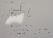
mosfet Rds resistance current sensing of FOC

Joined
Nov 26, 2019
Messages
96
for FOC control, I know ST developed a well good tool for 1,2,3-shunt current censoring, however there is a trend applying mosfet Rds on resistance current sensing technology, the well know case is the hoverboard at here:
https://github.com/lucysrausch/hoverboard-firmware-hack
see the mosfet Rds on resistance current sensing detail:
mosfet_Rds.JPG
also votol series EM-30s/50/100 using the same way, there is no mosfet current sensing resistor at all but one bus current resistor.

searching through the google/github I can't find any material explains this technical in detail, the hoverboard-firmware-hack does not really use the opamp for current sensing at all after I checked the source codes, it applies a very rough open loop/simplified current control method. obviously it has huge benefit if we can develop a generic firmware suitable for this topology. it is simple, less power consumption and very popular nowadays, can replace the original firmware keep using the decent hardware, box and terminals, while add more function eg. Bluetooth, CAN bus or even make it compatible with VESC tool.

anyone would like to share some more understanding on this detail?
 
I don't think this will ever become popular.

Why?

1) the Rdson of MOSFETs is not well controlled and changes a lot with temperature. Shunt resistors are designed to have low temperature coefficient.
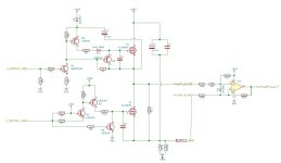
2) it requires an opamp with very fast recovery from overload at input and output saturation. When the low side resistor is off, the opamp is pulled strongly high. The diode across the inputs in the schematic above is what prevents rapid death of the device, otherwise the op would see the bus voltage at its input (through the 40kohms) and death would ensue.

From a control perspective this makes it very much inferior to other current control methods. It has a good case to make for itself as a protection strategy, say you monitor it when the low side is on (blanking when it's off) you could rapidly detect shoot through etc.

The technique is frequently used in ti dcdc converters where it provides either protection (that doesn't work very well...) or is used for very crude determination of on time/threshold switching methods.
 
mxlemming said:
I don't think this will ever become popular.

Why?

1) the Rdson of MOSFETs is not well controlled and changes a lot with temperature. Shunt resistors are designed to have low temperature coefficient.
2) it requires an opamp with very fast recovery from overload at input and output saturation. When the low side resistor is off, the opamp is pulled strongly high. The diode across the inputs in the schematic above is what prevents rapid death of the device, otherwise the op would see the bus voltage at its input (through the 40kohms) and death would ensue.

From a control perspective this makes it very much inferior to other current control methods. It has a good case to make for itself as a protection strategy, say you monitor it when the low side is on (blanking when it's off) you could rapidly detect shoot through etc.

The technique is frequently used in ti dcdc converters where it provides either protection (that doesn't work very well...) or is used for very crude determination of on time/threshold switching methods.

I disassembled a lot of ebike/escooter controllers, with different brand, that's why I say it is very popular, or I should say it is popular on ebike/escooter applications, the mcu used is stm32F103 or STM32F030.

I discussed it before see this thread,
https://endless-sphere.com/forums/viewtopic.php?f=30&t=106862&p=1666324#p1666324

scheme.jpg
Resistors not only the controller mentioned above but also those of the hoverboard are selected skillfully to pick up the correct Rds on voltage.

for the temperature coefficient issue, I noticed votol EM-30s has equipped with case temperature sensor, the mosfet are all soldered directly on the case, temperature compensation is possible if you want. on the other hand, using motor embedded hall sensor as a rough position detector, accurate current measure is meaningless.

the diode as you pointed out, is simply block the current sensing during low side mosfet off period, I do not see any issue on that.
 
The other issue is you need to take the measurement only at the right part of the cycle and blank the rest. I guess you can do this in software. The main advantage of this method is not needing shunt resistors to measure the current. You can save a few cents. The temperature coefficient might make the current drop a bit as it gets hotter, which could be a good thing. Nearly all the controllers I've dissected use shunt resistors. A few used hall effect current sensors. There is probably a reason for this.
 
Back
Top