Motor Current Limiting: More Power and Less Heat!!!

fechter said:
When the voltage drop across the shunt increases enough, the comparator threshold will be crossed, driving the output of the amp low. The diode conducts, pulling the throttle signal low. The resistor in series with the throttle signal limits the current on the output of the throttle hall to prevent overcurrent.

:arrow: How would you get overcurrent on the signal wire?

It's a 5 volt max system right? All the comparator can do is cut the throttle signal... hmmmm... I just don't understand it even though you've made what looks like an honest attempt at explaining it. I'm sure any knowledgeable electrical engineer would understand. :?

Maybe I need to get to a question that is more simple:

"Does the comparator simply 'chop' off the throttle signal whenever the shunt voltage is too high, or is there more to it?"

It seems like you've made a circuit that is very flexible, but harder for me to figure out.

Couldn't you use a comparator in such a way that when it "toggles" the result is like a relay that opens and the throttle signal is simply turned off. Even a relay could work I suppose and since those have long latency periods you would not have to worry about capacitors. Kind of a crude idea though... :shock:

Minimalist Idea

You simply use a small relay that runs on the shunt current. If the voltage goes high the relay opens and the throttle signal is chopped... when it goes low it closes. That eliminates the entire circuit! :lol:
 
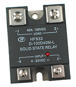
Solid State Relay

739px-Solid_state_relay.jpg


Why not simply take the shunt current and trigger a solid state relay?
 
No Throttle Connection At All? ... is this even Possible?

How about this. You take a relay that literally "chops" the motor wire. You place one of these between the controller and the motor and when the shunt delivers enough voltage to trigger the relay you simply "chop" the connection to the motor itself. The throttle and controller are no longer involved in the loop. (and can't get damaged or confused)

:arrow: Why wouldn't this work?


HFS33_250.jpg
 
A relay is on or off. There's no in between. The limiter circuit will be partially on during normal operation. The circuit will find equilibrium at a certain voltage for any condition.

You don't want to interrupt the motor circuit because you'll have mega high voltage spikes that would have nowhere to go. You'd also introduce extra losses and a triac solid state relay would get stuck on if you were at full throttle (they only work with AC).

The capacitors from the amp inputs to ground form a RC filter that filters the PWM switching frequency. You need them. The third cap that goes to the output side might be optional depending on how filtered the throttle input to the controller is. Most controllers have a circuit the limits the ramp up rate.

If you short the signal wire from a hall throttle, there's a chance it will damage the throttle, since it has a transistor output that will be working against a short. With the 1k in series, the most current the throttle will source is 5ma, which should be low enough to prevent damage.
 
I can see how cutting off the motor current isn't a good idea... I was looking up Solid State Relays and the heat dissipation is pretty bad. You end up losing something like 50 Watts in losses.

:arrow: So I can see I need to rule out the "No Throttle" idea.

But what's wrong with using a low voltage Solid State Relay to toggle the throttle voltage on and off? Instead of using the comparator you use a Solid State Relay. The throttle current is then either "on" or "off" depending on the shunt voltage. When the shunt voltage is too low it fails to trigger the threshold on the Solid State Relay and the throttle stays on. Once the shunt voltage rises high enough it triggers the relay and the throttle gets turned off. The only pot you might need is to get the shunt voltage to match the Solid State Relay. The relay might be losing a little energy, but it's coming from the shunt, so it doesn't really matter.

:arrow: So what about it? What's wrong with a Solid State Relay?

Conceptually it's a lot easier and would seem to be less likely to have problems of calibration... (only one pot would be needed) My brain comprehends a relay, the comparator with all the pots is confusing, so based on the fact I can understand a relay it makes that more attractive if it works.

:arrow: And what about something that behaves like a Solid State Relay, but the input voltage reacts PROPORTIONALLY to scale down the output? Something in a semi-conductor line of thought comes to mind. Basically this should be a very simple problem that is not unlike a thermostat that needs to know to turn off the heater when the temperature gets too hot.

There needs to be one circuit that you can buy that does most of the work...
 
A solid state relay typically needs over 3 volts to activate. We want something that responds to less than 50 mv. Something that behaves porportionally is the op-amp. I can't think of any other devices that would do the job easier. Possibly a differential amp made from bipolar transistors, but that's what's inside an op-amp anyway.

Op amps are fairly easy to predict and tend to behave well.

I'm open to suggestions.

The only thing that might be even easier would be to hack the circuit that already exists inside the controller. Of course, this is different for every model of controller.

The divider circuit in my schematic could be simplified more if you didn't need a porportional adjustment. If you just wanted a fixed, lower limit, you could eliminate one pot.
 
I guess the voltage that you get from the shunt is an order of magnitude lower than what you normally expect to feed into a Solid State Relay. This is true for many of the larger Solid State Relays, but I wonder if there is such a thing as a "very low voltage" Solid State Relay that only requires 50 mV? After all, the voltage we are dealing with is a pitifully small 5 volts on the output side.

:arrow: You do acknowledge the absolute simplicity of the concept, right?

If there was a Solid State Relay that could be triggered with only 50 mV this circuit would be a "no-brainer"... (so easy a caveman could do it)
 
Idea One: Shunt with a Low Current Solid State Relay?

VISHAY Intertechnology, represented by Soanar, has announced the VO1400AEFTR, a miniature 1-Form-A solid-state relay (SSR) with low on-resistance of 5 ohms, trigger current of 1mA, and load voltage of 60V.

Using an optical medium, the new device provides clean, bounce-free switching for indoor security, instrumentation, and industrial control systems.

Packaged in the 4-pin SOP, the VO1400s 4.7mm by 7.4mm footprint provides up to 75% space savings on PCBs, enabling smaller form factors for passive infra-red sensors, electronic access controls, test instruments, circuit board testers, and semiconductor test equipment.

The low input trigger current of the VO1400AEFTR makes it easy to interface the device to standard logic circuits, while the low output on-resistance and load voltage parameters benefit systems designed for low power operation.

The VO1400AEFTR is rated for an isolation test voltage of 1500V. Solid-state construction results in arc-free switching, magnetic interference immunity, and a longer operating life compared to electromechanical reed relays.

Samples and production quantities of the VO1400 are available now, with lead times of six to eight weeks for larger orders.

http://www.vishay.com/product?docid=84724

http://www.ferret.com.au/articles/51/0c044f51.asp
 
Idea Two: Hall Effects Sensor and a Solid State Relay?

If you took a Hall Effects sensor that produced 4 volts then you would be able to trigger the Solid State Relay.

Buy the right two components and they could work together... :wink:
 

Attachments

  • hall effect sensor.gif
    hall effect sensor.gif
    37.6 KB · Views: 2,057
Idea Three: Hall Effects Sensor and a FET Switch?

How about a Hall Effects Sensor that triggers a FET Switch?

:arrow: Does that make any sense?

When looking up Solid State Relays I was referred to FET's, so maybe they do essentially the same thing. Our controllers use FET's don't they? And if FET's can turn a current on and off based on the throttle signal then I would figure they could turn on and off a throttle signal if it's given a Hall Effects Sensor signal.

Seems logical... :?
 
The hall effect current sensor simplfies design quite a bit. I guess I should look at those more closely. It allows the design to be "dialed in" in advance, so guesswork about calibration can be minimized.

You could just drive a transistor with one, but I still like op-amps for some reason.
 
Hi guys.

I can't understand what you want to do.
I don't see speedmeter circuit at yours idea.

You get quite different efficiencies at the same motor current for two different speeds ( 5mph and 25mph for example).
Additionally at high grade slope - motor current limiter could push all things in bad direction: when the current limit will be to low to generate enough torque so speed start falling to zero and strat pulling the efficiency in the same direction.

So you need a pretty smart circuit which will set up the actual limit for the sake of actual speed and actual acceleration/deceleration.
So at high grade slope if deceleration occur the current limit will be pushed up to stop fast falling of efficiency. ( Efficiency will drop imediately as current will raise but after this drop, will be at higher level than the level which will be reached after speed fall.

What do you think about above idea ?
 
eP said:
I can't understand what you want to do.
I don't see speedmeter circuit at yours idea.

This thread is dedicated to the idea of reducing heat
and at the same time allowing more power in the top rpms.


To do this you change the way the controller measures current. In a standard controller the current is measured on the battery side and so it allows the current on the motor side to "multiply" based on the fact that when you chop the voltage to the motor the current increases proportionally... conservation of energy is maintained this way. If you measure and limit the current on the motor side itself then you get a constant amount of current to the motor and constant heat. In the high rpms the current remains below the current limit so the power is not reduced. The result is more power where you want it and less heat where you don't. This is only a good idea if you are using gears. Hub Motor users should disregard this thread because it does apply to you.
 
If heat is the central issue, then it might be more appropriate to limit current based on temp.

The question I see when measuring current, is that current must be raised when increasing load... otherwise, you can only cruise or slow down. The current increase will always give temperature rise for the period of increased load.

The tricky part is thermal latency... We regularly increase temps in our motors when we increase load: Usually, for short enough time that the motor can dissipate the heat. A system that manipulates current should measure temperature to reduce current. But, the system will never know how long a rider will call for more current... so it can either restrict current and reduce power... or allow current to exceed the temperature limit and let the rider take the risk of burnout.
 
safe said:
eP said:
I can't understand what you want to do.
I don't see speedmeter circuit at yours idea.

This thread is dedicated to the idea of reducing heat
and at the same time allowing more power in the top rpms.


To do this you change the way the controller measures current. In a standard controller the current is measured on the battery side and so it allows the current on the motor side to "multiply" based on the fact that when you chop the voltage to the motor the current increases proportionally...

Sorry man but You are totally wrong :!:

At the top rpms you have no "multiply" current as controller have to work at 100% Duty.
So the same current is on the battery side as on the motor side.

I see you want gears to keep rpms as high as possible.
As a consequence you get 100% duty and no multiply effect.

If the duty is much lower than 100% the multiply effect is important ( you should care about this effect ).
But this is not the case "top rpms".


safe said:

conservation of energy is maintained this way. If you measure and limit the current on the motor side itself then you get a constant amount of current to the motor and constant heat. In the high rpms the current remains below the current limit so the power is not reduced. The result is more power where you want it and less heat where you don't. This is only a good idea if you are using gears. Hub Motor users should disregard this thread because it does apply to you.

If you lower the speed (at high speed) you save the energy or you must reduce gear if you want high torque (at low speed) to lower motor current and saving energy this way.

But if you try limit the current you can get savings for the cost of acceleration.
If you driving at temporary constant speed or the speed is falling the current limit cannot give you savings at most cases in fact you will more waste instead as your rpms will falling faster then voltage sag at motor side so the efficiency will falling.

Rethink all again and try to simulate worse cases.

Regards
 
eP said:
At the top rpms you have no "multiply" current as controller have to work at 100% Duty.
So the same current is on the battery side as on the motor side.

I see you want gears to keep rpms as high as possible.
As a consequence you get 100% duty and no multiply effect.

This is true for the "perfect rider".

The "perfect rider" knows how to always be in the right rpms 100% of the time. The "imperfect rider" has a tendency to allow the rpms to drop and use that "bad and dirty" low rpm torque that has high values, but creates excessive heat.

The idea is to force an "imperfect rider" to be a "perfect rider".

Now does it make sense?

It's like the difference between the old Unix interface and the modern Windows computer inferface. The old way did get things done, but you had to be "perfect" in order to get it right.

:arrow: I'm creating a "user friendly" geared bike. (literally idiot proof)

It becomes "impossible" to make an error and produce excessive heat...
 
TylerDurden said:
The question I see when measuring current, is that current must be raised when increasing load... otherwise, you can only cruise or slow down.

Wow, you're not learning very fast on this one. :shock:

No offense, but stop and think a bit because you're repeating the same incorrect logic more than once. The "core principle" of gears is that you can CHANGE the torque without doing anything to the motor.

:arrow: The central geared bike axiom:

Rear Wheel Torque is the combination of Motor Torque and Gearing

So, when you have a large load you need to downshift... which lightens the load.

You have to get out of that "fixed gear" mindset... the world of gears has unlimited torque at the rear wheel... though you might find yourself climbing the hill at only 10 mph.

Lower gearing spreads the load out over time, thereby reducing it...

Ever hear the phrase "divide and conquer"? That's what gears do.

Slow and steady wins the hill climb race when you motor is small and your gearing is low... :wink:

 
safe said:
Wow, you're not learning very fast on this one. :shock:
Maybe so, but it is noteworthy that the rider who most recently smoked his motor suddenly became interested in an "idiot-proof" current limiter.

"Experience is a dear school..." said Franklin; there is a cooked Unite 750w motor somewhere that is a fine example.


So please explain to the rest of us philistines, how a rider will use this "new" concept in operation... how will they know when to shift down, when to shift up?

:?:
 
safe said:
This is true for the "perfect rider".
...
The idea is to force an "imperfect rider" to be a "perfect rider".

Now does it make sense?

Yes it does.

But this way you try to go you can create perfect idiot( or perfect blind) at the best case.
Because your circuit dont know actual rpm.

safe said:

It's like the difference between the old Unix interface and the modern Windows computer inferface. The old way did get things done, but you had to be "perfect" in order to get it right.

:arrow: I'm creating a "user friendly" geared bike. (literally idiot proof)

It becomes "impossible" to make an error and produce excessive heat...

The same way you could argue that half the voltage is more "user friendly" as naturally limiting max current.
The best "user friendly" is Zero Volt as the any user cannot waste any amount of energy :wink:
 
LEDs might work to indicate current-mode (cut or not-cut), but then what?

light on: downshift
light off: upshift

Hysterisis will need to be accounted for...

:?:
 
TylerDurden said:
So please explain ...how a rider will use this "new" concept in operation... how will they know when to shift down, when to shift up?

When the rider experiences no power he knows that it's time to shift down to a lower gear. The "feel" of accelleration is based on final power output, not just torque alone. The standard controller allows a very wide powerband so it "feels" the same across a large segment of the powerband because with "current multiplication" torque actually increases in absolute terms as you go lower in the rpms which compensates for the lack of overall power that lower rpms normally mean. Power is a concept that is difficult to understand, it has two components: torque and rpm. The fact that torque can be made to increase as rpms decrease is sort of "weird" compared to gasoline motors which are based on a direct relationship to number of "explosions" in the cylinders and actual power output. Anyway, when you deprive the "imperfect rider" of his low rpm torque then he "feels" the lack of "get up and go" and realizes that he has to downshift or the bike will simply stop accellerating.

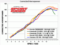
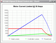
:arrow: The existing controller behavior is "ambiguous". You can't know by "feel" if you are in the high or low part of the powerband because it all more or less feels the same. (only at the extremes can you "feel" power dropping away) With the change I'm suggesting the powerband will look exactly like a motorcycle powerband with a very pronounced "peak" at the top and a very linear "feel" where the power builds and builds until a peak and then falls off.

Look carefully at these two charts. The behavior will "feel" the same on the modified electric bike or the gas powered road racing motorcycle... the rider will know what to do and when...
 

Attachments

  • motorcycle dyno.gif
    motorcycle dyno.gif
    24.2 KB · Views: 2,591
  • Motor Current Limit @ 50 Amps.gif
    Motor Current Limit @ 50 Amps.gif
    13.7 KB · Views: 2,591
Understanding Power

Power is made up of torque and rpms. It's a combined value. So it's possible to have high rpms and low torque equaling in power some other motor that has low rpms and high torque. Gears establish the relationship of motor speed to rear wheel speed, so a motor might spin at very high rpms and when you gear that down you magnify the torque it has in proportion to the gearing. With adequately low gearing you could climb a brick wall... obviously the traction would not be available, but the motor could do it...

There are many parameters that you can play with... :wink:
 
TylerDurden said:
When will a rider shift up?

If you've ridden a "peaky" motorcycle before (I've logged about 100,000 miles on such bikes in my lifetime) you know by "feel" that when the "peak" arrives it's immediately followed by a fall into a no power "no load" zone. So the "upshift" is easy to recognize because the linear rate that the power climbs suddenly falls away. The "downshift" situation usually occurs rather slowly as one begins to realize that the motor can't pull the gear you are presently in and you are forced to admit that a "downshift" is necessary. You can "feel" the difference between the motor ramping up and falling away verses it just sort of bogging down.

The "problem" with the existing standard controller behavior is that since the torque at low rpms is high and it drifts downward until the power "peak" you have a nearly flat powerband in the middle. There is little that you can "feel" because the torque decline with increasing rpms masks the effects of increasing power based solely on rpms.

:arrow: Did that make sense?

What makes the gasoline powerband easier to "feel" is that the torque is constant, but the POWER increases because it's a one-to-one relationship with rpms. Gasoline motorcycles are easy... more rpms equals more power.

The electric motor (as currently used with the standard controller) has the "current multiplication" that masks... it hides... the power "peak".

I've got a lot of experience in how gasoline motors behave and what I'm doing is bringing the benefits of that type of powerband to the electric bike. For "electric motor" purists this is an "abomination", but when you really start to look at how gears effect the electric motor you realize that "current multiplication" is a sort of "lower gear" for a hub motor. The ONLY (and I mean only) negative to this behavior in a hub motor is that it produces an inefficient type of power that uses a lot of energy and produces a lot of heat.

By removing "current multiplication" you lose that simulated "lower gear", but it doesn't matter for a geared bike because you have REAL gears that do the same thing. The geared bike gets it's "current multiplication" in a different way because it simply spins the motor faster using a lower gear. Since the motor is now spinning faster the current that is applied is used more efficiently.

Hopefully it all makes sense to you now... it's crystal clear to me and it's the only way to go if you are using gears.

The "bottom line" is that if you exclude "current multiplication" at the low end you can compensate by increasing the current limit "overall" because there is no longer a fear of someone dropping low in the rpms and burning up the motor.

Whew... :shock:

Take another look at the "standard" behavior. Notice how the curve for power is always "falling away". The "slope" of the power curve is always declining as you go up in the rpms. This tends to hide the power peak. The "sharper" the "edge" between the ramp up to the "peak" and the "no load" area the easier it is to "feel" your motor. Ideally the "edge" should be at least 90 degrees...
 
Back
Top