Motor Current Limiting: More Power and Less Heat!!!

Lowell said:
I was just setting up a nitrous intercooler sprayer on a customers car... how about a shot of cryogenic cooling along with unlimited motor amps? :twisted:

Now that's cool! 8)
 
20hp/lb :shock:

Now where to put the liquid nitrogen...

http://www.grc.nasa.gov/WWW/RT/2003/5000/5930brown.html

On a more practical level, paintball CO2 bottles are cheap to buy and fill. A nitrous purge solenoid to control flow, and a small tube run to the motor.
 
fechter said:
They're using liquid hydrogen. After cooling the motor, run the H2 gas to a fuel cell :D

Is a fuel cell ebike legal? Local laws here specifically ban on board generators, but I think that is aimed at people who want to put gasoline generators on their ebikes.

My style would be a hydrogen rocket motor :lol:
 
safe said:
eP said:
So tell us what is the nominal Power_out of that motor, and how much is efficient at 0.2 HP light load ?
I'm afraid it is big P_out motor and its efficiency at light load is pretty low.
But maybe i'm wrong ?

Here's the idea... take this motor:
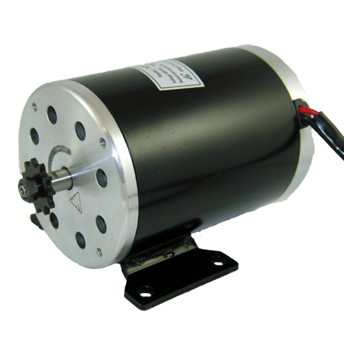
106155.gif


MY1020Z3 36 Volt, 750 Watt, 2800 RPM, 27.4 Amp

...and overvolt it to 48 volts. Then start to play around with the controller logic as I've done over the course of this thread.

You can recreate everything I've done starting from scratch if you desire... :wink:

You then overvolt that motor to 48 volts which doesn't change the key parameters like the motors resistance, but does increase the no load speed in direct proportion to the voltage increase.
Brushed motors start arching and create more brush friction the faster they go.Gear boxes have the tendency to to raise in drag after they hit there rated rpm as well.Not to mention early failure.
 

Safe, I hate to admit it, but I think you're on the right track.

In fact, I've already done your idea of using a 7 speed gear hub with the exact motor you pictured. It plows up hills, and when I get my shifter attached, I anticipate that it should go about 35mph on flat. (lots of wind resistance in design) I already love the thing.

I'm going to put pictures and video up soon.

As soon as I'm done, I'm going to be trying to do exactly what you're describing.

My next project, will be modifying a CVT transmission to maximize the effeicency of the motor. I plan to remove the weights that make it "change gears" and control the gearing with a microchip.

I read your discussion, and I think you only need sensors to get two numbers:

1) The speed the bike is traveling
2) The gear ratio it's using

You can work backwards to get the motor rpm from these numbers.

The mph can be found using a hall effect sensor like speedometers use. The microchip will be controlling the position of the cvt using a stepper motor, and it will constantly be moving it and keeping track of the movement.

I agree with you that using gears that span a 300% range should suffice for all situations. So, by that thinking, you don't need to concern yourself with managing the electric current. For example, if you're going up a steep hill, the microchip will start downshifting until the motor is running in its peak effiiency, and it will chug up the hill. As long as it has the proper gear to work with, it should adjust automatically to avoid the overcurrent situation (or you could just limit it).

I think the easiest way to do this is to use a 2hp motor, and a controller that will max-out at 1 1/2hp. Then just don't worry about it.


The program would work in two stages: When you first accelerate, it will be in the lowest gear, and the entire acceleration will be from the motor. This would last until about 15mph. Then the motor would stay at a constant rpm, and the bike would spped up by adjusting the gears (CVT).

I was going to suggest that this is a "gear based throttle."

This process could be entirely managed by the microchip. In fact, I plan to just a on/off throttle. You push the button to go faster, and release it to coast. The microchip would manage the acceleration, it wouldn't just "floor it." It would incrementally increase voltage when the bike is ready to go to the next speed. There could easily be a cruise control button too.

My dream scenerio would be to use this motor:

<a href="http://www.thunderstruck-ev.com/sailboatkit.htm">Mars Motor</a>

which should be about 90% effient to start with. Use a 60 amp controller, so it would never break a sweat. That scooter would go forever.

Now all I have to do is build it! (I haven't even posted my first project yet!)
 
The only question I would have is that if you really do go ahead and get a CVT and figure out computer control that will fix the rpms of the motor is such a way as to be "ideal" then why would you even need "Motor Current Limiting"?

Your idea is actually "better" because it avoids the bad rpms entirely. With "Motor Current Limiting" it's still possible to "bog down" into the lower rpms, but you are very aware of it and know when to downshift. With a CVT system as described you are always properly geared so you essentially never see those low rpms.

So I appreciate your compliments, but I think your system will be superior in the end. However... "in the end" means that you actually get all the bugs worked out and get it working.

:arrow: Sometimes the practical issues of "how do I do it?" play a role in design... the "Motor Current Limiting" concept is fairly simple to do...
 
Time and Speed

From Zero to 40 mph it will only take about 22 seconds. But to get from 40 mph to 50 mph it will take almost as long again. (16 seconds)
 

Attachments

  • Time and Speed - Motor Current Limited.gif
    Time and Speed - Motor Current Limited.gif
    12.7 KB · Views: 2,776
This is a comparision of the "Motor Current Limited" acceleration from Zero to top speed verses the "Battery Current Limited" controller. Notice how at the very beginning the "Battery Current Limited" gets a jump off the line but by the time you get to the higher gears that advantage is already gone and when it comes to top speed the "Motor Current Limited" can pull a few more miles per hour. If this were a racing situation you would not get a good start (with this gearing) but on the straight aways (which will seem long on such a low powered bike) you will have plenty of time to draft and have that extra few mph of top speed to get by. In a "real world" race the drafting will dominate... it's a little like NASCAR once you get going... :wink:

The shifting points would be the same since above the power peak the powerbands are identical... (the higher top speed for the "Motor Current Limited" bike is because it's power peak produces more power)
 

Attachments

  • Time and Speed - Comparison.gif
    Time and Speed - Comparison.gif
    6.7 KB · Views: 2,769
Here's a first pass at a schematic using the Allegro ACS755 series current sensor. The current sensor could be installed in either the battery or motor wire in a brushed system. This will only work on the battery side for a brushless system. It's possible to design it to work on the motor side of a brushless system, but I'll look at that later.

The ACS755 series is available in a number of different capacities. The sensor should be chosen to have slightly higher capacity than the controller.

The current adjustment will go from full (whatever the sensor is rated for) to nearly zero. The adjustment range is a function of the resistor divider on the + input.

The parts should be available at DigiKey or Mouser.
 

Attachments

  • Safe Current Limiter.jpg
    Safe Current Limiter.jpg
    27.8 KB · Views: 3,991
Safe:

Look at the efficiency chart of the Unite motor you pictured:

<a href="http://www.unitemotor.com/unite/en/Products.asp?ClassID=055110929001904">Unite Motor Chart</a>

Notice that this motor's peak efficiency is at 82%. This must be under a significant load because it is very similar to the "rated load" line. Also notice that the effiency of the "no load" line is 34%! So the really bad area is the "no load" zone. The "max torque" situation isn't even so bad--the efficiency only drops to 70%. The one thing that all the more efficient lines have in common is that they all have rpms around 2800.

So, as long as you keep the rpms up, and a decent load on the motor (using gears) it seems like you should stay in an efficient zone.

Also, I already have a CVT at my house, and it looks great except for the fact that it takes a bit of effort to spin it. It's such a cool device, I'd hate it if looses a bunch of energy to friction.
 
Beagle123 said:
Notice that this motor's peak efficiency is at 82%. This must be under a significant load because it is very similar to the "rated load" line. Also notice that the effiency of the "no load" line is 34%! So the really bad area is the "no load" zone. The "max torque" situation isn't even so bad--the efficiency only drops to 70%. The one thing that all the more efficient lines have in common is that they all have rpms around 2800.

So, as long as you keep the rpms up, and a decent load on the motor (using gears) it seems like you should stay in an efficient zone.

In case you were wondering... the reason my charts don't show the full efficiency is that I subtract the controller losses (5%) and chain losses (another 5%) from the starting motor efficiency. So while the stated efficiency is a little above 82% the "real world" efficiency is closer to about 78% or less. Since I'm overvolting this motor in the simulation the starting efficiency began at nearly 85%.

Anyway... there are many ways to figure efficiency depending on whether you want to think in terms of "at the motor" or "at the rear wheel".

:arrow: Which CVT do you have at home now?
 
fechter said:
The ACS755 series is available in a number of different capacities. The sensor should be chosen to have slightly higher capacity than the controller.

The current adjustment will go from full (whatever the sensor is rated for) to nearly zero. The adjustment range is a function of the resistor divider on the + input.

Looks like a big improvement. The ACS755 seems to allow you to "phase out" two of the pots so that you have gone from what appears to be three pots down to one.

Am I reading this right?

:arrow: Only one pot?

I might be able to live with this...
 
Rear wheel horsepower is what counts, and what will move a bike down the road. As long as the efficiency numbers state whether or not those losses are accounted for though, it's all good.
 
This is the CVT I have:

I may just try it "as is" first to see how it works with its own gear shifting formula. I'm not sure how it will work. This is from a pocket bike. I beleive the model is x8. However pocket bikes operate at about 5000 rpm, so I don't know how it will work.

THe gear ratio is about 2:1 between the belts. That will switch to 1:2 at high speeds. Also, this one has built in gear reduction to the sprocket that's about 3:! so when I turn the motor shaft one turn, the sprocket turns about 1/6 of one turn.

I may just use the parts to build my own contraption.


Update: I found my wrench!!! It was next to my CVT!!! I was looking everywhere for that thing!
 

Attachments

  • DSCN0371.JPG
    DSCN0371.JPG
    53.7 KB · Views: 2,698
  • DSCN0373.JPG
    DSCN0373.JPG
    56.6 KB · Views: 2,698
safe said:
Since I'm overvolting this motor in the simulation the starting efficiency began at nearly 85%.

Are you sure - the stator has the margin enough to be overvolted 100% over the specs (nomen-omen :wink: ) safely ?

Do you know what hapend if you overvolt the core inductor which have no enough margin to be overvolted ?

If you don't - ask the fechter.

The 85% efficiency are the "papers" efficiency at that case i'm afraid.

How do you think why Unite don't overvolting his 24V motors to 48V at specs for better efficiency ??

Are you really think they are so stupid they don't know where are the real limits of the stator ?
And they don't know at what voltage they can get the max. efficiency ?
 
Beagle123 said:
I may just use the parts to build my own contraption.

Update: I found my wrench!!! It was next to my CVT!!! I was looking everywhere for that thing!

It takes an impact wrench to get those nuts off.. and that is just the beginning of your headaches after you get inside of that thing.

Please, post some pictures of the guts.

I've been there, and several others have too. This particular type of CVT is very lossy and hard to tune for electrics.

My advice:

Do yourself a huge favor -throw that thing as far as you can and focus on a fixed gear, or geared hub set-up.


-S
 
It takes an impact wrench to get those nuts off.. and that is just the beginning of your headaches after you get inside of that thing.

Please, post some pictures of the guts.

I've been there, and several others have too. This particular type of CVT is very lossy and hard to tune for electrics.

Yea it looks like a huge headache, but I like a challenge.

Were you trying to electronicly control the gears? What were you and the others trying to do?

I was thinking of just using the pulleys off it and attaching a stepper motor to control the gear ratio.

What do you think about insstalling it "as is" by just attaching a motor to the drive shaft, and letting it do all the work? Would that be better?

Thanks for the input.
 
eP said:
Are you sure - the stator has the margin enough to be overvolted 100% over the specs (nomen-omen :wink: ) safely?

My motor is rated as 36 Volts and I was looking to overvolt it to 48 Volts.

:arrow: Let's recap what a motor does. There are two forms of energy losses, there is the BackEmf which can be "conquered" with more voltage and then there are the (stator) resistance losses. As you push more current through the wires you get more heat... but if you increase the voltage in the wires the heat does NOT increase. So increasing the voltage is actually a way to get more power without damaging anything. (that's why racing classes are based on VOLTAGE... higher voltage is always better)

Heat is based on the formula:

Current (squared) times Resistance

...so if you can LOWER the current you LOWER the heat.

Actually... what would be another thing to experiment with would be to look at just how much overvolting I could get away with before the rpms get so high that gearing becomes impossible.
 
Beagle123 said:
Yea it looks like a huge headache, but I like a challenge.

If it is designed for a motor that revs to 5000 rpms you should switch to another motor. The geared motor you are using is perfect for the multispeed hub, but it doesn't look like a good match for that CVT.

You probably realized that already... :wink:
 
safe said:
eP said:
Are you sure - the stator has the margin enough to be overvolted 100% over the specs (nomen-omen :wink: ) safely?

My motor is rated as 36 Volts and I was looking to overvolt it to 48 Volts.

:arrow: Let's recap what a motor does. There are two forms of energy losses, there is the BackEmf which can be "conquered" with more voltage and then there are the (stator) resistance losses. As you push more current through the wires you get more heat... but if you increase the voltage in the wires the heat does NOT increase. So increasing the voltage is actually a way to get more power without damaging anything. (that's why racing classes are based on VOLTAGE... higher voltage is always better)

Heat is based on the formula:

Current (squared) times Resistance

...so if you can LOWER the current you LOWER the heat.

Actually... what would be another thing to experiment with would be to look at just how much overvolting I could get away with before the rpms get so high that gearing becomes impossible.

Hi Mate.
I see now you are novice :(

Do you know what is the reason the startor is builded with many thin steel sheets ?
The same is true for 50/60Hz transformers.

The stator's Fe loss is quite different than winding (Cu) loss.
I'm not fluent in english so i can't quickly show you why you are wrong. I'm sure you are able to find righ materials or some native speaker can explain you all very precisely with right links. (Maybe Fechter or somebody else )

Best Regards
 
safe said:
...so if you can LOWER the current you LOWER the heat.

If you lower the current, you get less torque.

SO:

How low can you lower the torque (current) and still be able to accellerate?

Lowest torque (Nm)?

Lowest current (A)?

:?:
 
96 Volt Insanity?

Okay... "Motor Current Limiting" does a great job of keeping under control the motor heating. What about Voltage? What if you go "big" with the voltage on a small motor and go "small" with the current using a combination of a very low current limit and "Motor Current Limiting" to keep the heat down to an absolute minimum.

The biggest problem I can see is that a motor that is originally designed to spin at 3350 rpms is all of a sudden running at 8933 rpms.

:arrow: Question to the "brain trust":

If current is low, heat is low, and the only thing to fear is speed itself... could such an idea work?
 

Attachments

  • (8933 rpm) 96 Volt @ 30 Amps - Crazy.gif
    (8933 rpm) 96 Volt @ 30 Amps - Crazy.gif
    8 KB · Views: 2,582
TylerDurden said:
If you lower the current, you get less torque.

Still haven't figured out power yet huh? :lol:

Torque is an "instantanious" value. Power is the combination of torque and rpms. Run high rpms (volts) and you get more power. Gear that down and you get more power at low vehicle speeds.
 
eP said:
Do you know what is the reason the startor is builded with many thin steel sheets ?
The same is true for 50/60Hz transformers.

The stator's Fe loss is quite different than winding (Cu) loss.

I was assuming that when you said "stator" that you really meant "rotor" (where the current flows) so I was trying to communicate with the language you seemed to have presented.

The stator is just the permanent magnets.

:arrow: So what are "trying" to say about the "permanent magnets"?

The motors we use don't manually energize those magnets so there is no current wasted doing anything to them. They just "sit there" and behave magnetically and cause the BackEmf.

You seem to be off on what we call a "wild goose chase" focusing on something that doesn't appear to be a major factor in the formulas that motors use to figure out their powerbands.

:arrow: BackEmf = VoltageConstant * Rpms / RadiansSec

:arrow: Current = ( ActualVoltsUsed - BackEmf ) / Resistance
 
Back
Top