So, I'm checking the design of a motor for an EV, as a sort of feasibility study while I decide what to do with my broken car. Some numbers don't seem to add up, so if anybody spots any mistakes, I'd be very thankful. I'm an EE, but I've not had to compute this stuff for an electric motor since classes a decade ago, and feel like I have forgotten more about this stuff than I ever learned.
Here the basic assumptions:
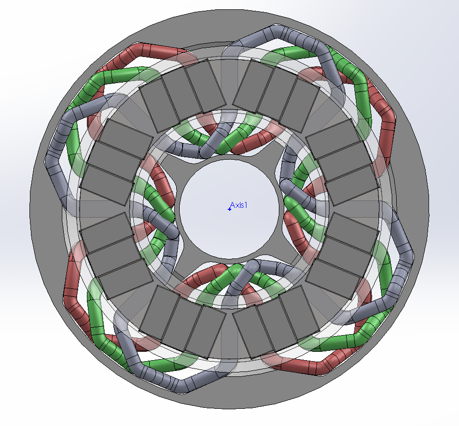
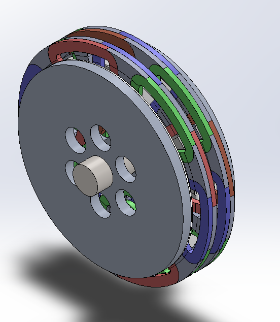
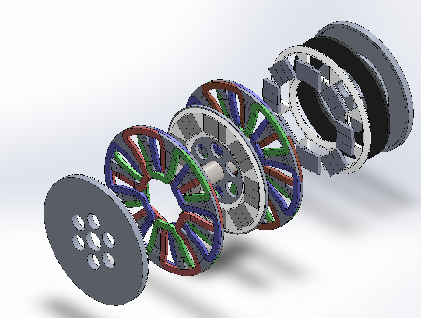
I decided the rotor diameter should be about 200mm, for an air core axial flux PM motor with stator sandwiched by two PM rotors. Doing a simple CAD layout, an 8 pole / 3 phase wave winding seems reasonable. Coils are made to have 50mm^2 cross section. I have 30x15 N42SH magnets available. The Google tells me that for a 50mm^2 cross section of copper, about 100A current sustained seems reasonable.
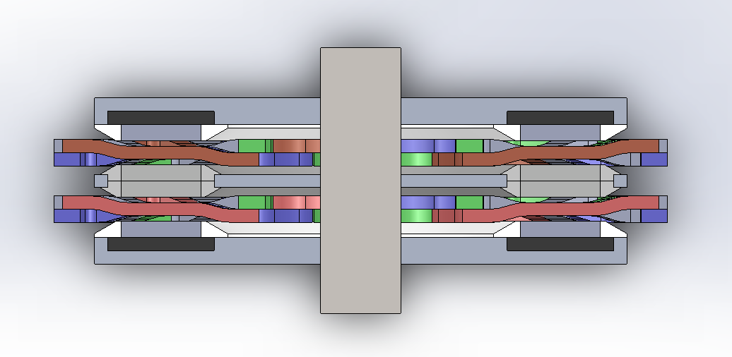
I've made the winding in the relevant segments of the stator to have a rectangular cross section, 5mm deep and 10mm wide (and 30mm long). Total gap between rotors is thus 9mm, with 2mm air gap on each side of the stator. A quick FEMM simulation told me to expect a top field strength of about 0.5T from the magnetism, provided a 5mm steel backing plate . FEMM also tells me that for 100A, about 1.5N of peak force per phase per pole, for a total of 12N per phase, [strike]which translates to 160Nm torque[/strike] (EDIT: the torque was wrong, its only 0.9Nm), assuming the effective/mean radius of the motor is 75mm (200mm outer diameter, 10mm inset for the 30mm magnets, so 150mm mean diameter). The FEMM numbers are also what I got from calculating manually, based on a current carrying wire in a static magnetic field.
This being a wave winding, I have to admit I hadn't had a clue how to compute its inductance. My classes on this subject are long in the past, but if I'm not completely mistaken, assuming its a 150mm diameter ring should approximate it nicely, which puts me at 4uH inductance for a single turn, and about 7mH for 50 turns of wiring. I figured I'd aim for 6000rpm top speed, so I computed a 400Hz self induced EMF of about 35V @ 50T and 0.75V @ 1T, which seem reasonably little that I won't be worrying about this any further.
As a sidenote, at 6000rpm there's considerable load on the rotor, but nothing to worry about at this point.
The more interesting thing is the dynamic EMF from the magnets. For a single turn of 30mm length wire, I get about 0.7V @ 400Hz. For the 8 pole wave winding, this results in 5.6V back EMF on a single turn, or for the 50T version, 35V and 280V respectively. The ohmic resistance of the wiring is 0.24mOhm for 1T, and 600mOhm for 50T.
(EDIT: solved via fixing torque, yay!)[strike]Now, this is the point where I don't see the numbers adding up. 160Nm @ 6000rpm are roughly 100kW mechanical power, but how does this compute electrically? From no electrical property do I see where the 1000V @ 100A for 100kW power are supposed to come from. I'm clearly being a dunce and I'm skipping a step or doing something wrong somewhere, maybe something about the dynamic interaction of the magnetic field / voltage / current?[/strike]
Here's a view with the rotor disc being semi-transparent, magnets, and the stator coils behind:


