Thud
1 MW

This will be the build log for the small "test Mule" Axial flux motor.
Objective- To learn as much about motor design & application as possible.
On my recent build I am quite pleased with the performance of my relitivly tiny RC outrunner motor. with the experiance gained I realize I will need much more power for my next build, Since I make things for a living, I thought, why not make the motor I want?
Here is a list of issues from my perspective:
1) RPM's- They are extream,freash charge voltage spins the 50mm outrunner at 12700.
This is an niose issue more than anything else. An open can whistling away,as well as the additional reduction
parts spinning at dizzying speeds-We need Tourque at a resonable rpm
2) Size- the outrunner I selected was size specific to cram into the rear triangle of a small bicycle frame. The
larger motors that have enough power create other issues, width moves most out of the crank circle.
I think thiner is a winner if we are not going to settle on a hub motor.
3) Controllability- As much as I love my sensorless RC controllers, I know they are stressed beyond there design intent. The smaller sensored controllers are going to provide a few more options regarding the performance envelop on this & future builds.
This motor is described as "Single rotor axial flux/split stator" There may be other topologies attempted latter, we will give them their own desin specifc attention when the time comes.
I wish I could list the expected performance numbers. There are too many variables inplay right now to speculate. The mule expectations are to match the 50mm outrunner for tourque(or at least 80% of it) & get the Kv as low as posible.
Progres:
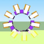
rotor construction-
.5"dia x .25"t Neo-magnets n42 (or n48-i forget)12lbs pull force each. Aluminum hub & outer retainer ring

here it is with epoxy resin & fillers for securing the magnets

I Use my printer for a lot of layout work on most of my projects these days. print a 100% scale picture & rubber cement it to some plate & chop away.
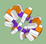
Here is the rotor with the shaft pressed into it & the motor cases roughed out.

& here it is along side some other motors for scale.

After finishing the case (bearings & coil anchor points) its on to the stator teeth.
Dollar totals for the build thus far-$100.00 (magents & 12lbs of magnet wire)
 It's ok, because we have lots of alphabet left, and you've got myself and other more smarty-pants guys to help us arive at the goal on one of those letters.