Doctorbass
100 GW
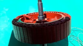
Sprayon emal rust protection
I used this kind of protection on every of my hub motor and never experienced any problem with them.
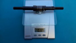
I also replaced the 13 gauge ( that look like 14 gauge) by real phase wires 10 gauge direct from in and out of the axel! This shold be overkill for a 4T motor and itMS ... just ... perfect !
Tomorrow i will try adding find on the inside of the side cover and will paint in black with the Krylon Ultra flat black paint that is also good in the IR range for the emissivity.
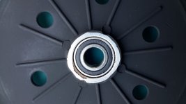
I have baked the paint to 100 degree C for about 8 hours. This dractiscly change the hardness of it and it is more robust and will not easy scratch when magnets rotor will be reassembled together.
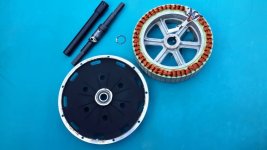
I also painted the rotor magnets as a well as the steel expose area. But i have baked it at 60 Celsius to avoid demagnetizing magnets.
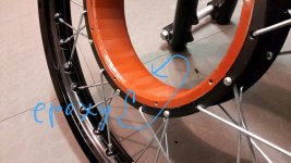
I have added DP420 epoxy to the side of all magnets and also in the crack between eahc magnets si water can not infiltrate and magnets will NEVER unbound due to rust that could push on the bottom of the magnets and unbound them like it happened for few members here. The rim you see is the 19 inches x 1.6 sold by John Holmes that i will install a heavy 5 pounds Sinko 241 on it.
Doc
Doc
I used this kind of protection on every of my hub motor and never experienced any problem with them.
I also replaced the 13 gauge ( that look like 14 gauge) by real phase wires
Tomorrow i will try adding find on the inside of the side cover and will paint in black with the Krylon Ultra flat black paint that is also good in the IR range for the emissivity.
I have baked the paint to 100 degree C for about 8 hours. This dractiscly change the hardness of it and it is more robust and will not easy scratch when magnets rotor will be reassembled together.
I also painted the rotor magnets as a well as the steel expose area. But i have baked it at 60 Celsius to avoid demagnetizing magnets.
I have added DP420 epoxy to the side of all magnets and also in the crack between eahc magnets si water can not infiltrate and magnets will NEVER unbound due to rust that could push on the bottom of the magnets and unbound them like it happened for few members here. The rim you see is the 19 inches x 1.6 sold by John Holmes that i will install a heavy 5 pounds
Doc
Doc
Attachments
-
 20150716_124013 (Personnalisé).jpg127 KB · Views: 3,065
 -
 20150716_124033 (Personnalisé).jpg116 KB · Views: 3,065
 -
 20150716_124055 (Personnalisé).jpg114.4 KB · Views: 3,065
 -
 20150716_124121 (Personnalisé).jpg99.5 KB · Views: 3,065
 -
 20150716_124130 (Personnalisé).jpg84.1 KB · Views: 3,065
 -
 20150718_004812 (Personnalisé).jpg58.8 KB · Views: 3,062
 -
 Studio_20150718_005014 (Personnalisé).jpg57.1 KB · Views: 3,062