My 48v 500W Cruiser Chopper Project

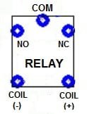
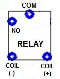
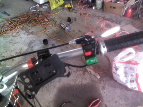
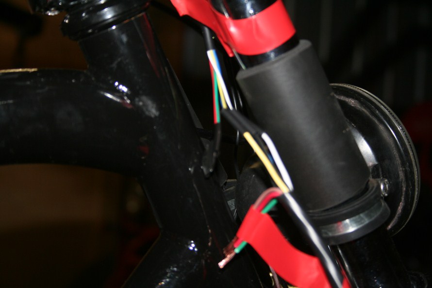
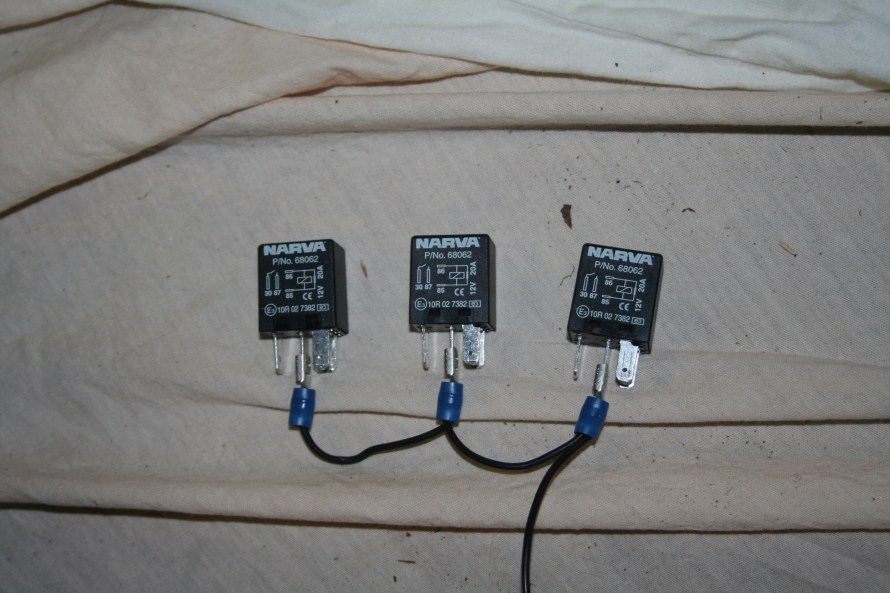
Hey mate, thanks for that. I was not sure the pinouts of the program relay but I wired it in the same way I used to with for lights, if i remember correctly I used it as a 4 pin relay, where the relay was powered with +which was controlled by the switch and - directly from the battery.

The relay was then used to provide a direct input from the battery which through the relay would be normally open, when the 12v was applied by completing the switch connection it would close the circuit. This way the switch wouldn't be taking the main load of the headlight, only to provide a small amount of 12v to power the relay
 
I got started today with some scrap 7 core wire that I found lying around, so I decided to strip the insulation around it and started to route the wires around the frame. I believe i’ll need 3 relays so far, 1 for the horn, one flasher relay for the indicators and one for the front head light. I’m still debating the need for a relay on the front headlight due to the tiny 1 amp draw on it.

I found the perfect spot to put the relays. Under the seat there is a considerable amount of space to hide the relays and other bits of electronics required so it should be a really neat install (except for the main wires to the horn/indicator/light switch itself)

img_20120715_151521.jpg


Here hs my faithful trailer on the back of my chopper. I reassembled the fabric portion after attempting to dye the fabric. I believe the fabric itself is coated with a waterproof material and this could have stopped the dye from sticking. The windows did tint up nicely though haha

img_20120715_151509.jpg


Visible below is the switch that I bought off ebay for the headlight, indicator and horn. The unit fits really nicely over the brake lever

img_20120715_151556.jpg
 
I made a bit more progress today and it seems like my wallet took a bit of a beating haha.

I bought a whole bunch of bolts for the torque arms and the P clamps that will be used to hold on various other components to the frame.

I ended up mounting the headlight, i've used the 2 fork tubes with the use of a pair of P clamps. The ends of the P clamps had to be grinded away as it was fouling against the mounting points on the headlight, I got to use my new vice finally (i've always wanted one) and was happy to see that the bench in the garage has 2 holes already drilled to mount the vice. It still needs some work and i'll need to align it downwards a bit more.

img_2219.jpg


img_2220.jpg


img_2221.jpg


Here I am doing some wiring at the front of the bike. I am still working out how I will route the wires. At the moment I am using 7 core trailer wire which supports 5 amps per wire.
img_2223.jpg


img_2228.jpg


Here is a pic of under the seat where I will mount the required relays.
img_2224.jpg


My Cycle Analyst Arrived today, it is huge. I was expecting a tiny little screen but this is massive haha.
img_2226.jpg


I was working on a way to daisy chain the earth wires for the micro relays that I bought. I was thinking of using a Y shape (but with 3 wires) for the positive input wire (the one that supplies the actual light, horn etc) to ensure that each relay will get a solid supply. Even with the indicators and headlight on full I am not likely to use more than 2amps in total. The horn will still need to be worked out.

img_2222.jpg


A better photo of my awesome kids trailer which has been "tinted" with black fabric dye haha
img_2227.jpg
 
Scruffoid said:
I dunno I cant see a trailer all i see is a workbench :)
Haha I always seem to mix around the photos.

I got word from the supplier that my motor kit is nearly ready, cinhis has been fantastic to deal with and also arranged to supply a wide tube and tyre for me.

Hopefully I can finish my torque plates before it arrives.
I might test out my cycle analyst today too
 
circuitryn.jpg
[/quote]

amberwolf said:
Question: In the Relay symbol, it has three connections on top and two on bottom. Usually a relay uses the two for it's control, the coil, and three for it's load--one Common center, one Normally Open, and one Normally Closed. So I'm curious if that program does or doesn't do it that way, or if it is simply not using the likely more intuitive layout of grouping the control and load connections separately?

Hmmm... I was thinking the same thing myself. On a standard 5-terminal relay, typically the (+) and (-) terminals for the coil are grouped together on a relay and the COM, NC, and NO terminals form another group as shown...
 

Attachments

  • Relay1.jpg
    Relay1.jpg
    5.1 KB · Views: 3,096
Hey All,

its been a while since i've made my last post, i've been super into pedal power on my new road bike and got my ebike buzz back now (after i'm so exhausted all the time lol)

I have been speaking with Jason at Conhis motor and he has been absolutely awesome to deal with. He has made me a custom 20x4.25" 48v 500w hub motor package and it looks stunning.

I can highly recommend anyone looking at getting any custom work to definitely have a chat.

img7793oz.jpg


img7792i.jpg


I am still not quite happy with my current battery supply since it is quite wide. I may end up putting this 48v 15ah in the trailer and get another 48v 10ah or better laid out 48v 15ah to take its place on the frame itself.
 
Hey all,

Just a quick update. I have test fit the hub wheel and so far everything seems nice and neat. I routed the wires to the controller and disconnected the pas sensor and brake levers with the switches. The new conhis meter has a 5 step battery indicator and a key switch (which feels like a real motorbike now haha).

The controller is luckily the same size as the previous one that I had, so this will sit very neatly just in front of the back wheel.

I'm still a bit iffy about the battery that I have here, i'm sure its fine but its just the wrong size to fit somewhere on the frame.
 
This is possibly the most frustrating thread I have ever read! You have 2 electric hub wheel kits, a 16ah battery pack, a CA and other ebike items but have never built the bike up and never felt the ebike grin!!! Get it done man!
 
AussieJester said:
+1 there's also a hand full of other threads with issues that could have been And some IIRC have...on several occasions been answered here ...get it done man...

KiM

Yeah I am sorry about the frustratingness of the thread, I look into things a bit too much.

I didn't end up keeping the 16ah lifepo4 and rear hub motor, but I still have my front hub motor. Planned completion is 2 weeks. You have my word :)
 
Good weather is here so like to see you having fun on it, I was almost going to suggest putting the 20ah pack in the trailer but its gone, good luck mate
 
Thanks for that :)
After speaking with the manufacturer of the hub motor they mentioned they wouldn't recommend running the 48v 500w hub motor on a 24v 500w controller. I may have sourced some 24v batteries and wanted to get it going at least, and changing the controller to a 24v 500w one was the best option to suit the batteries.

The manufacturer mentioned that it may damage the wires, the motor and effect the life of the motor. not too sure about those details. If I remember correctly a hub motor can run on a variety of voltages, its the controller that would change those specifications.

I'll get this front hub motor going either way, and then I can save up for a 36v 500 or 1000w rear hub wheel in 20x4.25" properly this time.
 
The winding of the motor determines its speed for a given voltage. A motor wound for 48v will run slowly on 24v.

Apart from that, a "48v" controller will run just as well as a "24v" controller, set up to put out a similar level of current. Getting a 24v controller is mostly a waste of time.

If you are like me and don't want to mess around with lipo balancing etc, just get a 48v LiFePO4 battery and be done with it. Given the gearing and geometry of that bike (cruiser rather than racer), it is possible you will be happy with the performance without going for a rear motor.

Higher performance motors are for higher performance bikes. :wink:
 
Back
Top