My unplugged ESC blew up and dumped me on my face @ 30KM!

KeeweeNZ

100 µW
Joined
Aug 5, 2014
Messages
7
Hi Guys,

This is my first post on this forum, however i have been following for awhile.

A friend and I have built a couple of longboards using the ever popular SK3 motors, we used 245KV 6364 motors for a good balance of torque and speed.
The boards have been going great and I've been loving riding it, however today I went for a couple of KM blast around a local pond/estuary. I must have miss judged how full my batteries were coz i ran dry half way round. I thought " no problem ill just unplug and push the old fashioned way" meanwhile my mate was powering along no trouble :(.

Anyway to get to the point I came to a decent down hill and footbraked the first 20m to avoid some pedestrians then tucked in for the speed... i got to about 30km then out of the blue the drive wheel locked and threw my ass headfirst down the hill.
I ripped my nice jeans, got covered in mud as i slid a couple of metres on asphalt then into the dirt verge on the side of the path. it was a good stack and I have no idea why it happened.
When I collected myself, picked up the battery and cover for my transmitter that ejected on impact, I checked the motor and wheel to see if they turned and they did. but it was like the brake was on you could clearly feel as the motor resisted turning.

I decided to plug in and power up the ESC to see if it still worked and immediately it made the motor jerk funny then magic smoke appeared :(

My only idea is that because i was hitting about the same speed as the flat max speed under power, the generated current from the motor was too much and the reverse voltage fried the FET's and caused two windings to short, essentially slamming on the brakes.

has anyone else experienced this? should more people be aware that this can happen? i got off lightly with missing skin and ripped clothes but it could have been much worse!

I'm using a trackstar 150a GEN2 esc and the above mentioned motor on 5000mah 6s lipo and to confirm the batteries were disconnected from the ESC (Positive unplugged).

Please provide any insight you may have :)
 
Sorry to hear about your damage. :(

One of my belt drive bikes with RC motor and ESC has no freewheel. If it is not powered up and you push it along at a brisk walking pace, you suddenly hear the arming melody from the esc. (motor obviously works as a generator)

I have not coasted along without being powered up - thanks for this post, now I'll make sure I never attempt that.
 
Sounds like you had 2 phases short to each other.

When you unplugged, are the phase plugs capable of touching on the motor side? If so, that's what happened. If not, it could be an internal short (inside the motor) on those phases.

use a DMM to test for a short
 
I would guess that as the OP theorized, since the ESC had nowhere to put the generated voltage, without a battery connected to it, then the voltage went higher than the FETs could handle and popped one (or more).

Even if the ESC doesn't normally support regen braking, the motor itself will still generate a voltage (higher the faster it spins) and the FETs would still act like a rectifier bridge, and if a battery was connected then it would probably have been ok and the voltage would've been kept low enough by the load of the battery charging up. But it would also have put drag on the wheel, too.

Next time (if htere is one) I'd recommend unplugging the motor from the ESC instead of the ESC from the battery (or do both), so that hte motor can't generate a voltage across stuff inside the ESC. Just make sure you have some sort of plug covers for the motor phase wires so they can't accidentally short across each other, or you'll still end up the same way. ;)
 
amberwolf said:
I would guess that as the OP theorized, since the ESC had nowhere to put the generated voltage, without a battery connected to it, then the voltage went higher than the FETs could handle and popped one (or more).

Even if the ESC doesn't normally support regen braking, the motor itself will still generate a voltage (higher the faster it spins) and the FETs would still act like a rectifier bridge, and if a battery was connected then it would probably have been ok and the voltage would've been kept low enough by the load of the battery charging up. But it would also have put drag on the wheel, too.

Next time (if htere is one) I'd recommend unplugging the motor from the ESC instead of the ESC from the battery (or do both), so that hte motor can't generate a voltage across stuff inside the ESC. Just make sure you have some sort of plug covers for the motor phase wires so they can't accidentally short across each other, or you'll still end up the same way. ;)

Oh, he didn't unplug the motor from the ESC, but just the battery. AH... my reading comprehension needs some work today :oops:

Good thing Amberwolf is all over it.
 
That sucks! I wonder if this could happen to all of us? I'm Using mostly Castle ESC's but have one EZrun Pro too. My esc's have a voltage cut-off so my boards just shut down @ 3.4v. I've always switched them off and pushed home. Should I actually just be leaving the switch in it's on position instead? Would that eliminate the possibility of this kind of short since the batteries are low anyway?

This topic needs discussion. :shock:
 
YEs i suppose this could happen to everyone, remove the belt is the best solution for free roll.. two nuts to save your face! or get really good at nose manuals
 
onloop said:
YEs i suppose this could happen to everyone, remove the belt is the best solution for free roll.. two nuts to save your face! or get really good at nose manuals

You don't think leaving the circuit open (switch on) would be a solution? Or removing the belt is the only sure fire way to eliminate the possibility.

Has anyone used or made a freewheel motor pulley?
 
Thanks for all the kind words guys,

I'm good, nothing that won't heal or that I haven't previously done worse some way or another :) i'm stoked that i didnt rebrake my collarbone as im still technically on a take it easy period after having the plate from a previous MTB accident surgically removed a couple of weeks ago! mainly it was just a good elbow, knee and hip scrapes and bruises, cut up palms and bruised thumbs from putting my hands down at that speed.

since my first post i've done a full dissasembly of the board and checked everything over. it was definitely an electrical lock-up and I have given the motor a good once over. it's fine although the force of the lockup squashed the ends of the primary pulley grub screws so that had come loose aswell.

I dissasembled the ESC and 5 out of 6 fets on one phase (on one side of the pcb) were completely toast ie casings cracked one even spat out all its legs and there was little balls of solder all through the esc.

my esc doesn't support regen braking but after the dissasembly and talking to some electronics guys i think amberwolf has hit the nail on the head, the generated voltage from the motor was enough to backfeed through the esc and destroyed the fets which caused an internal short and essentially just applied full brakes.

I must say i'm now a little sketch about this happening again while its running (ie, esc connected to batteries and powered up) does anyone know if this is likely or possible or when the batteries are connected and the esc is on, is it safe to bomb decent hills?

I am going to machine a plastic holder that seperates the motor wires and in future any unpowered pushing will be done with the motor disconected from the esc. or i will leave the esc on and avoid bombing big hills.

the only reason i wasnt just pushing with the esc on is that i still havent recieved the PC programming cable for the esc and the factory settings have a 10% drag brake enabled and thats a real pain in the ass when trying to push against it.

With my setup removing the belt is a bit harder because my freind and i have designed out motor mounts to have a bearing cap that supports the free end of the motor shaft and covers the primary pulley, this is to extend the motor life by preventing side loading of the motor as they are only designed for axial loads and the cover also makes it much less likely for bouncing stones to get into the belt further reducing the chances of damage or an unexpected lockup.

I plan on taking some good shots of our parts tomorrow while they are all apart (mainly for my design potfolio, both of us are product development engineers for a large company here in New Zealand and are qualified industrial designers), since we got alot of inspiration from this site it seems only fair that we share the developments we have made as I haven't seen anyone else do some of the stuff that we have done and I feel it really adds to the durability and efficiency of the boards. Let me know if you would like to see the images and if there is a want, i will put them up :)

once again, thanks for the kind words and if anyone can confirm that it is safe to exceed the flat land max speed of the board when bombing hills when the ESC is on and hooked up that would be a great piece of mind!

so far this has been a reasonably painful and expensive learning exercise (even having worked 3.5 years in the hobby industry i had never seen this sort of thing happen before) nut it would be good to get some answers so at least a few of us know what to expect and avoid doing :)

Cheers guys
 
psychotiller said:
onloop said:
YEs i suppose this could happen to everyone, remove the belt is the best solution for free roll.. two nuts to save your face! or get really good at nose manuals

You don't think leaving the circuit open (switch on) would be a solution? Or removing the belt is the only sure fire way to eliminate the possibility.

Has anyone used or made a freewheel motor pulley?

I have drawn up some designs for a freewheel pulley using a one way bearing however you loose the braking ability and thats one of the things I like best about the e-board.
 
Everyone loves a picture! Put some up if you can :)

I was just thinking how to test the scenario you were in, but without a 30km face plant - and my best idea was to get the board on a powered treadmill....

Totally feeling your pain, I came off the other day thanks to a damn stone under the wheel. Probably only about 20kph, but enough to join your battle scar gang....wrist, knee, shoulder and a Wife not looking very pleased with me :lol:
 
Pediglide said:
psychotiller said:
Has anyone used or made a freewheel motor pulley?

What? You did not know mine has them? :D

That's right! I do remember you saying you had them. You'll have to let me check it out.
 
I posted this a while back. You have to be careful about going too long without using your esc. I had two instances. Once while using my MTB. I had hooked up only one motor to see what the speed difference is. I was using the esc for the one motor on another board at the time, so it was just one side setup and the other had the motor mounted. I was riding around enjoying myself and after about ten minutes of riding the board stopped. I couldn't figure out what happened. I checked everything, rode off and just thought I'd hit something in the road. Rode around for a few more minutes and it did it again. Finally figured that the lone motor was getting enough juice to try and start up on its own. Sketchy.
Then testing the boat ESC, I did a bunch of hills to see if the ESC would get hot. Same deal, enjoying riding down the hills and then all of a sudden the board stopped. I checked everything again and rode off. It did it again another time before I realized what was happening.
Now when I ride those same hills, I give it throttle every once in a while to keep things in check. I try not to go too far without clearing out the extra juice that's being feed back into the ESC. If you run out of battery and are pushing I'd do the same thing. Give it throttle every hundred feet or so. This might be one issue where a regen system would help.
Glad you survived. I've had enough weird things happen on a board that I try and keep the speed down.
 
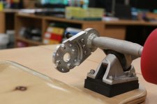
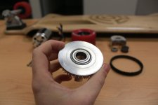
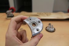
Ok since a couple of people are interested, here's some pics of the setup that we have designed and built.

Main differences from most builds are:
- Bearing cap to support free end of motor shaft (these are aircraft motors designed for axial loads not side loads and the amount of force running through these setups is HUGE therefore supporting the free end of the shaft should significantly increase motor life)

- Bearing supported drive pulley - once again the loads experienced by these boards is pretty huge especially under braking, by incorporating a bearing that supports the drive pulley we have balanced the force that would try and cause the wheel to rack and potentially cause belt alignment issues. lets be honest skateboards aren't the most precise machines and unless you have your wheel bolts up way too tight there is quite a bit of play in the wheels. This bearing also allows us to assemble the belt and everything before we put the wheel on and probably the best bonus is we no longer need a retension plate on the outside of the wheel to hold the pulley in place, which makes the whole board look soo much cleaner.

- Motor locating features - because we have designed the belt adjustment into the motor mount we do not need the motor screws to be able to move/slide therefore we have created features on the mount that physically interlock with the front plate of our motors, this means the motor is definitely not going to shift and the bolts holding it on are only required to do just that.

- Aesthetics - Making it look nice is important as we are both industrial designers, we wanted to make sure that we didn't ruin the look and feel of the longboard by putting a motor on it, so we have done everything we can to minimise the visual impact to the board. I think we have achieved this, there are no unsightly protrusions from the bottom of the deck and visually the parts work well together ie, bearing cap to wheel gap. the only bit we have not yet finished is the battery pod which is going on the top of the deck and will be a structural carbon fibre piece that will still let us wedge our feet up against so we can get as planted as possible when boosting around. It will follow the lines of the board and will be pretty low profile.

- Drop Deck boards - We chose drop deck boards because we wanted the ultimate riding experience, the drop deck allows a lower centre of gravity and provides a better turning response at speeds and also the drop sections are perfect for planting your feet into, we also got the boards crazy cheap which helped.

All the design, machining and manufacture has been done by ourselves including the welding etc.

Let us know what you think and feel free to ask if you have any questions, like I mentioned above - we got a lot of inspiration from this site and what others have done before us.

file.php

file.php

file.php

file.php

file.php

file.php

file.php
 

Attachments

  • All parts compressed.jpg
    All parts compressed.jpg
    93.6 KB · Views: 863
  • motor mout motor side compressed.jpg
    motor mout motor side compressed.jpg
    63.7 KB · Views: 863
  • motor mout back side compressed.jpg
    motor mout back side compressed.jpg
    61.2 KB · Views: 863
  • motormount assembled motor side compressed.jpg
    motormount assembled motor side compressed.jpg
    68.3 KB · Views: 863
  • motormount assembled pulley side compressed.jpg
    motormount assembled pulley side compressed.jpg
    64.2 KB · Views: 863
  • truck side mount compressed.jpg
    truck side mount compressed.jpg
    66 KB · Views: 863
  • truck side mount machined surface compressed.jpg
    truck side mount machined surface compressed.jpg
    62.2 KB · Views: 863
here's the remainder of the photos as I had some trouble putting them up first off :)

file.php

file.php

file.php

file.php

file.php

file.php

file.php

file.php

file.php

file.php

file.php

file.php

file.php

file.php


Unfortunately the parts don't look as new as they did when fresh off the machines as they have already seen about 50km of use and the only thing worse than New Zeland roads are New Zealand footpaths!

I didn't get a good shot of the feature working, but the interlocking features between the bearing cap and the motor mount lock the parts together so there is no way for the cap to move around and allow stress on the motor shaft.
 

Attachments

  • 8 - assembling motor into locking features compressed.jpg
    8 - assembling motor into locking features compressed.jpg
    60.3 KB · Views: 863
  • 9 - Drive pulley back side compressed.jpg
    9 - Drive pulley back side compressed.jpg
    60.1 KB · Views: 863
  • 10 - Drive pulley wheel side compressed.jpg
    10 - Drive pulley wheel side compressed.jpg
    70.3 KB · Views: 863
  • 11 - motor and pullyeys installed compressed.jpg
    11 - motor and pullyeys installed compressed.jpg
    75.3 KB · Views: 863
  • 12 - clearances compressed.jpg
    12 - clearances compressed.jpg
    71.1 KB · Views: 863
  • 13 - bearing cap external compressed.jpg
    13 - bearing cap external compressed.jpg
    55.7 KB · Views: 863
  • 15 - bearing cap installed compressed.jpg
    15 - bearing cap installed compressed.jpg
    71.2 KB · Views: 863
  • 16 - Fully assembled compressed.jpg
    16 - Fully assembled compressed.jpg
    72.8 KB · Views: 863
  • 18 - fully assembled on wheels compressed close side.jpg
    18 - fully assembled on wheels compressed close side.jpg
    78.9 KB · Views: 863
  • 19 - fully assembled on wheels compressed rear side.jpg
    19 - fully assembled on wheels compressed rear side.jpg
    79.7 KB · Views: 863
  • 20 - fully assembled underside long view compressed.jpg
    20 - fully assembled underside long view compressed.jpg
    65.2 KB · Views: 863
  • 21 - rear shot on wheels.jpg
    21 - rear shot on wheels.jpg
    64.8 KB · Views: 863
Looks great! Great job.. Amazingly close to the trucks. I like how you are able to use a deep pocket board.

You have a bearing on the drive wheel pulley just spinning on the hanger? Is the hanger completely even? Did you even out those trucks? Looks like it.

Is your motor pulley free spin around the shaft or do you have a set screw on it so it's secure to the motor shaft?

The other pulley on the motor cover is to keep the motor shaft in straight alignment?
 
Thanks Guys,

We're pretty stoked with how the boards turned out :)

@torqueboards: the bearing in the drive pulley sits on a area that we lathed so it was a perfectly parallel cylinder if you look closely at the motor-mount that is welded to the truck hanger you can actually see it was welded on both sides and then the pulley side weld has been lathed back for the bearing. In my initial attempts to work out how to lathe the truck hanger (its not easy with the pivot spinning around much wider than the axle area) I initially lathed the wrong side of the truck. that's why the other side is also perfectly cylindrical I just evened it up and bead blasted the hanger to even it all out.

The pulley on the motor shaft is the drive pulley and by definition must be fixed to the motor-shaft: we have achieved this via two 180 degree opposed 3mm grubscrews they are drilled and tapped between the teeth on the pulley and locate on flats that we have cut into the motor shaft. because they are recessed into the pulley when tight they don't seem to affect the belt at all.

The bearing in the cap over the drive pulley is there to eliminate any side loading on the motor, these motors we're designed for propeller powered aircraft and so are designed to have a force pulling on the shaft along the direction of the shaft. by putting a load on the motor that pulls the shaft sideways we (most e-board riders) are putting a large force on the motor that it was not designed to take and therefore does not have the correct shaft support to handle. with the extra bearing in the cap we now have the shaft supported either side of the drive pulley and the motor see no sideways bending forces. the cap also protects the belt and makes it much less likely for a stone or other debri to get caught between the belt and pulleys

the motor is indeed very close to the truck and you can see from the sticker that when the motor slipped on the mount and loosened the belt during initial testing, the motor actually rubbed on one of the truck bolts.
there was supposed to be slightly more clearance but i welded the mount about a degree to to far around toward the base of the truck. if you look closely again you can see that i have actually used a large linisher to sculpt a bit of a curve into the truck base for clearance. as it is now, as long as the motor doesnt slip we dont get any motor rub and still have a great turning cirlce.

Another thing we did that was quite cool was to use a laser cutter to engrave the pattern onto the bottom of the decks before we varnished them. They originally came with a really average painted job and illustration rather than the polished wood you see now.
 
Wow, that's an awesome design and execution.

Well done. :mrgreen:
 
Glad you are OK
The only sensible solution is to wear full body armour at all times :D
ScreenHunter_179 Aug. 11 19.46.jpg
 
Back
Top