
Cool. You might be able to tie a throttle into the PWM and make the thing into a brushed motor controller with boost.
You are using an out of date browser. It may not display this or other websites correctly.
You should upgrade or use an alternative browser.
You should upgrade or use an alternative browser.
Need help with a 24V to 48V boost converter.
- Thread starter TylerDurden
- Start date
TylerDurden
100 GW
This looked like an interesting project:
http://www.virtintern.duke.edu/2003fall/solder/links/simulation3.htm
http://www.virtintern.duke.edu/2003fall/solder/links/simulation3.htm
jackatfsi
10 W
Ok...I've ordered this from EBay to open up and try to convert.....

TylerDurden
100 GW
Cool...
I have two or three cheepie 400w here I can crack open to compare with.
Thanks!
I have two or three cheepie 400w here I can crack open to compare with.
Thanks!
I have several of those in various stages of explodedness.
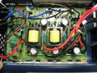
The 12vdc goes into a 12v to 160vdc transformer based converter with some nice big capacitors that charge up to 160vdc when you turn it on. From there, FETs chop the 160v to the output.
If you could change the transformer, you could get any voltage you want.
The transformer is fairly small and runs at a high frequency.
jackatfsi
10 W
Did you see what they did about 12V current limit and/or frequency control ?
Oh !......and was the output transformer center tapped ?????????????
(if not...much easier than rewinding)
Oh !......and was the output transformer center tapped ?????????????
(if not...much easier than rewinding)
TylerDurden
100 GW

xyster
10 MW
You know you're a geek if:
your idea of porn is close-ups of naked electrical components.

I'm a geek.
your idea of porn is close-ups of naked electrical components.
I'm a geek.
TylerDurden
100 GW

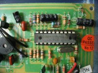
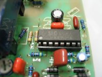
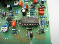
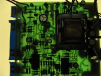
Good pics, I like the one that's backlight to show the traces.
OMG, the 400w one has the same PWM chip as a Crystalyte controller. How funny, they must be dirt cheap.
Interesting how the 700w one has 3 separate sections apparently in parallel. Hmm.... 3 phase.
In both cases, they use transformers. To radically change the output voltage of the dc-dc section, I think the transformer would need to be rewound or replaced. Since it runs at high frequency, the transformer might not have very many turns, so rewinding might not be that hard.
The big high voltage capacitors are the output from the dc-dc converter section, and this is voltage regulated at 160+V. The inverter section is just a FET bridge that switches the output. You could cut the 60hz drive to the inverter FETs and feed them with a PWM controlled by a throttle.
This might be perfect for one of those cheap 120v treadmill motors.
jackatfsi
10 W
fechter said:Good pics, I like the one that's backlight to show the traces.
OMG, the 400w one has the same PWM chip as a Crystalyte controller. How funny, they must be dirt cheap.
Interesting how the 700w one has 3 separate sections apparently in parallel. Hmm.... 3 phase.
Shore looks like 3 phase, donut !!
fechter said:In both cases, they use transformers. To radically change the output voltage of the dc-dc section, I think the transformer would need to be rewound or replaced. Since it runs at high frequency, the transformer might not have very many turns, so rewinding might not be that hard.
I'm still thinking maybe a center tap (or break) and rectify to 60+ volts....
fechter said:The big high voltage capacitors are the output from the dc-dc converter section, and this is voltage regulated at 160+V. The inverter section is just a FET bridge that switches the output. You could cut the 60hz drive to the inverter FETs and feed them with a PWM controlled by a throttle.
16 volts ????
fechter said:This might be perfect for one of those cheap 120v treadmill motors.
Don't know how long it'll take for the inverter to get here..but I'm pretty sure I have one of those treadmill motors out there somewhere...I better get lookin.......
jackatfsi
10 W
Inverter is here...

A typical cheapie inverter (modified sine wave) converts the 12v to around 160v before chopping it. Yes, 160v. Don't touch it. 160v is around the peak to peak voltage of a normal 120v sine wave.
The trick will be to PWM the voltage in order to throttle the motor.
The trick will be to PWM the voltage in order to throttle the motor.
jackatfsi
10 W
Yup !
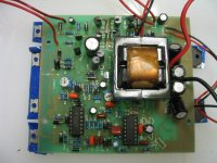
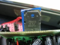
The first stage is just a push-pull pair of IRF1404 (Rds = .004) w/ a 40A fuze for limit.
The transformer has three secondaries. Two are connected in series, and the third is not connected at all. The output feeds a full wave bridge (4 diodes) followed by a 100mmF/200V cap. (presumably the ~ 160V DC ??)
There is a thermister controlled fan on the transformer.
I'm hoping to find ~80V per winding.....maybe tommorrow will tell.....
The output switches are 4 IRF640B. There are 4 IC's and 9 transistors. It will take a bit to work back through this baby!
fechter said:OMG, the 400w one has the same PWM chip as a Crystalyte controller. How funny, they must be dirt cheap.
Without exaggerating to much, I think the 3525 switching regulator can be found in every Korean & most Japanese VCR power supplys ever made. Along with the TL494, both of them date back to about 1980 if not earlier. It's a basic PWM building block that the design hasn't needed to change any. Safe to say the development costs have been re-couped.
jackatfsi
10 W
The 4 IC's are: 2 KA7500C, an LM393N and an LM324N.
A quick check of the transformer output shows 160VAC on the unconnected winding, 140VDC (no load) at the output of the diode full-wave bridge........(on the center-tapped ?? winding)
I have no idea of what the current rating of the "extra" winding would be ????
A quick check of the transformer output shows 160VAC on the unconnected winding, 140VDC (no load) at the output of the diode full-wave bridge........(on the center-tapped ?? winding)
I have no idea of what the current rating of the "extra" winding would be ????
jackatfsi
10 W
Ok.....revised transformer outputs after scoping at the output side of the transformer.......
There are three output windings.....they all put out a chopped AC ripple w/ no load applied to the AC output.
Under AC output load they all put out a square wave at 33.3KHz
The unconnected winding gives 40V P-P
One of the serial windings gives 140V P-P
The other serial winding gives 100V P-P
The two serial windings together give 240V P-P
A possibility is to rewire the output windings as 140V P-P and (40 + 100)V P-P...........running these in parallel for 140V P-P to the bridge diodes for 70VDC out....
Any thoughts ???
TylerDurden
100 GW
Would it be possible for you to sketch it up?
I was absent from electronics class that day... ok I never actually ever showed up.
But I could send it to people who went to school.
:?
I was absent from electronics class that day... ok I never actually ever showed up.
But I could send it to people who went to school.
:?
jackatfsi
10 W
Here's what I got so far on the 12VDC to 120VDC part....

Good sketch!
That's reverse engineering in action.
I wouldn't put windings in parallel unless I knew they were identical and properly phased. I does look like you could move the tap on the secondary to get a lower voltage to the bridge rectifier.
As I recall, usually there's some feedback somewhere to keep the output regulated. It might be an optical isolator. You could possibly mess with the feedback to vary the output voltage slightly.
To make a motor controller out of it, I would keep the dc-dc part pretty much intact and try to add a PWM to the output FETs.
You might make it work by messing with the dc-dc, but in order to get lower voltages, it will need to run discontinuous, which will reduce the power output at lower voltages. This would make for poor acceleration, but power would go back up at higher speeds.
jackatfsi
10 W
Ya...it'll take some more thinkin...to get full power at all speeds....still, even if I just rewind for 48V I'd be ahead of the game by eliminating the relay switching !
There is another KA7500C in the AC modulation section and 4 IRF640B's so there is the possibility of some proportional charge sharing...caps are cheap !
And nothing says the diodes (and their voltage) drop have to stay!
There is another KA7500C in the AC modulation section and 4 IRF640B's so there is the possibility of some proportional charge sharing...caps are cheap !
And nothing says the diodes (and their voltage) drop have to stay!
jackatfsi
10 W
My guess this morning is that the 2 comparators on the KA7500C are used to monitor the battery voltage and the input current limit. The 1200 watt peak rating must depend on stored circuit energy ??
Controlling on the input current limit would give a power control.
Looks like the transformer secondary should be optimized for desired top speed.
That leaves the AC section free to be used for some sort ??? of DC ?? auto-impedance matching network for the load ( Vout = 0.6I + Vb volts for the Heinzmann) ?????
jackatfsi
10 W
Here are some charts of what estimated data for the Heinzman hub motor should look like......


TylerDurden
100 GW
Interesting how efficiency seems to always get good in the lethal voltage range...
8)
8)
jackatfsi
10 W
fechter said:Good sketch!
That's reverse engineering in action.
I wouldn't put windings in parallel unless I knew they were identical and properly phased. I does look like you could move the tap on the secondary to get a lower voltage to the bridge rectifier.
As I recall, usually there's some feedback somewhere to keep the output regulated. It might be an optical isolator. You could possibly mess with the feedback to vary the output voltage slightly.
To make a motor controller out of it, I would keep the dc-dc part pretty much intact and try to add a PWM to the output FETs.
You might make it work by messing with the dc-dc, but in order to get lower voltages, it will need to run discontinuous, which will reduce the power output at lower voltages. This would make for poor acceleration, but power would go back up at higher speeds.
Ok...but just using the up-converter section as a current limited power (current at fixed voltage) controller......and rewinding w/ 2 24volt secondaries...........for the Heinzmann motor I get something like....

Edit: Looks like I should work on a tapped winding that might put some boost in at 36 volts ??????
Similar threads
- Replies
- 6
- Views
- 752
- Replies
- 8
- Views
- 597
- Replies
- 8
- Views
- 1,246
- Replies
- 8
- Views
- 1,448
- Replies
- 6
- Views
- 3,135