New 2017 updates to ebikes.ca motor simulator to try out

Looking into it some more; ive got reason to believe that the 500amp-turns / mm of 80C neodymium is actually on the conservative side; and as such the 170Nm might actually be attainable for the grin all axle?

And if thats the case, im pretty sure nobody actually ever demagnetized an ebike motor, unless it was by running it up to 120C magnet temperature, or a fault that shorts their phases when going at speed.

But its quite frustrating, that I cannot find any empirical data as to what is safe, demagnetization wise, in a reasonably controlled experimental setting. If anyone knows of any crumbs of information, ill happily take them!
Check this out:

 
Check this out:


Yeah im aware of what the basic physics looks like on paper.

But how does it actually play out in the real world, with a real rotating motor, tooth geometry, flux focussing, uneven distribution of flux over the surface of the magnet, etc?

You know whats funny? I can find recent publications of authors who claim that demagnetizing a motor with q-axis current is mathematically impossible; and those writing long articles under the definite assumption that it is very much possible. That seems to be going on for more than a decade... so I dont think another back of the envelope calculation is going to convince me either way... it sounds a little absurd but im starting to get convinced someone is going to have to actually hook up a motor to a test stand to settle this debate.
 
But its quite frustrating, that I cannot find any empirical data as to what is safe, demagnetization wise, in a reasonably controlled experimental setting. If anyone knows of any crumbs of information, ill happily take them!
Here are some crumbs from quite a few years ago that could shed light, which shows non linearities in the torque vs current curve maybe starting at about 60 Nm for the 9C style direct drive motors but it's really hard to extrapolate much from there:

The test methodology I used there wasn't very useful since at the current levels being applied to hit the 2nd order saturation/demagnetization effects, the motor windings are heating up EXTREMELEY fast. You only have a few seconds to do the test, and then wait a pile of time for it to cool down. Mind you this was all pre-statorade.

A better test would be to have a very high current motor controller (like 200-300A phase current) and hook up the motor to a large flywheel, then apply very short duration pulses of energy and track the acceleration of the flywheel to compute the actual torque that the motor was applying during these short bursts.

Or even better would be if someone has proper finite element package that has all the nonlinear magnetic charactristics modeled who could then load up the approximate motor parameters and tell us!
Thanks; those high amps are actually interesting to me though, heating notwitstanding. Im working on a project to optimize the whole powertrain for electronic braking; and its not so hard to design the setup such that the thermal mass of the copper alone suffices to buffer the entirety of the kinetic energy you are trying to get rid of; especially of a good chunk of it goes back into the bus.

At 60A or so, the MMF of the PMs still dwarfs the MMF of the amp-turns; so I would not expect nonlinearities related to saturation be a huge thing yet... assuming its a motor that is optimized for decent iron losses it should not be trying to push near 2T in the first place.

Good to know that its indeed quite linear up to those levels experimentally. That does give me quite some confidence that it should be fine up to 2x those levels. Ive been looking more into the demagnetization limits... and as I understand it now that shouldnt be the issue here; if you keep the magnets under 80C and you dont blast them with some crazy short circuit current we should still be some 4x away from those limits... I think.

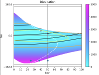
Ive been working on a motor simulator that ill soon open source, to crack braking torque, which was otherwise hard to get much information on. Its not at all the case that just knowing your Kv-line in the motoring quadrant will give you a decent stab at knowing what the braking torque quadrant looks like (which was a delusion I was laboring under until recently); and its very amenable to optimization; if you tune your L and R just right to bounce your beck-emf into your q-axis you can get some serious braking torque over your entire nominal speed range.

(brake pad manufacturers will really hate this one weird trick...)
 

Attachments

  • Screenshot 2024-06-28 at 20.52.10.png
    Screenshot 2024-06-28 at 20.52.10.png
    524.1 KB · Views: 5
Back
Top