New controller did not come with power line cable inside

Duttliam

10 µW
Joined
Jul 11, 2024
Messages
5
Location
Oshawa
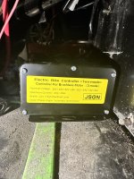
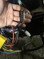
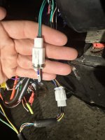
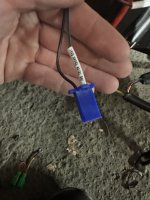
Hello, I am having issues with changing my controller on my DAYMAK road warrior. Every cord except 3 fit in the designated slots, but I have to cut the end off my brake, and phase metre and put the end from old controller on. And the new controller does not have a power line cord to go into the slot of my previous controller. Also my old controller does not have these 5 wires with rings at the end so I had to buy a 5 slot junction box so I can use this controller.

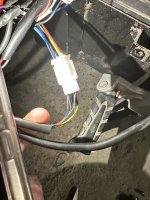
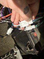
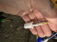
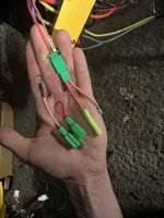
I have an option cord slot with different changeable ends, and that option cord is a red and orange wire labeled automatic doors. And one of the option ends for the orange side is the same end I could use for the power line cord. Would I be able to just use this option slot cord as my power line? And would I need to take the red end out of the option connection or just cover it up so there is no arc
 
We will need good photos of the controller label, controller wires and connectors, and the existing bicycle wires and connectors to successfully help you.
 
I was able to hook the controller up to the bike, but my throttle does not work I am assuming the throttle wires for the controller are in a different order then the throttle cables on the bike? I will take good pictures of everything right now
 
In this message I will take pictures of all the wires that were connected to the old controller (minus the alarm wires) only 1 wire from old controller is not connected because I do not know what I can connect to it, power line did not come on the new controller, or anything with the same end.

With all the different colors of wires I cannot figure out what goes where, I have a wiring diagram for my controller if you want pictures of that, but I have no wiring diagram for the DAYMAK road warrior and cannot find one online to compare how the wires are set and if I needed to move any around in the clips.

Photo 1: Controller details
Photo 2: reverse gear
Photo 3: throttle handle
Photo 4: three speed gear
Photo 5: haul sensor (every wire on each insert are matching colors)
Photo 6: junction box
Photo 7: high brake (purple to green with yellow stripe)
Phase meter (brown spliced to orange to purple)
Photo 8: power line (old controller had one going into this but new one doesn’t have anything labeled power line).
I had to splice the wires on the controller for high brake and phase meter as the ends did not match the ends on the bike.

Please let me know if you need better pictures, and of what. I will make a second comment attached with pictures of the wires I have not connected to the ebike
 

Attachments

  • IMG_5457.jpeg
    IMG_5457.jpeg
    1.9 MB · Views: 7
  • IMG_5466.jpeg
    IMG_5466.jpeg
    773.6 KB · Views: 7
  • IMG_5465.jpeg
    IMG_5465.jpeg
    1.3 MB · Views: 6
  • IMG_5464.jpeg
    IMG_5464.jpeg
    1.3 MB · Views: 6
  • IMG_5463.jpeg
    IMG_5463.jpeg
    1.4 MB · Views: 6
  • IMG_5462.jpeg
    IMG_5462.jpeg
    1.3 MB · Views: 5
  • IMG_5461.jpeg
    IMG_5461.jpeg
    1.3 MB · Views: 5
  • IMG_5460.jpeg
    IMG_5460.jpeg
    1.3 MB · Views: 7
Okay after reading this instructions again I just don’t understand because on step 3 it says it’s not nessessary to have a vehicle with a door lock but the door lock needs to be wired with the junction box parallel to the positive.. but then step 6 is telling me I need to activate the power to the door lock to get the controller to learn with intelligent identification.. any suggestion what I would do
 

Attachments

  • IMG_5482.jpeg
    IMG_5482.jpeg
    1.8 MB · Views: 2
  • IMG_5483.jpeg
    IMG_5483.jpeg
    1.9 MB · Views: 2
  • IMG_5484.jpeg
    IMG_5484.jpeg
    1.9 MB · Views: 2
  • IMG_5485.jpeg
    IMG_5485.jpeg
    1.6 MB · Views: 1
  • IMG_5479.jpeg
    IMG_5479.jpeg
    1.6 MB · Views: 2
In this message I will take pictures of all the wires that were connected to the old controller (minus the alarm wires) only 1 wire from old controller is not connected because I do not know what I can connect to it, power line did not come on the new controller, or anything with the same end.

With all the different colors of wires I cannot figure out what goes where, I have a wiring diagram for my controller if you want pictures of that, but I have no wiring diagram for the DAYMAK road warrior and cannot find one online to compare how the wires are set and if I needed to move any around in the clips.

Photo 1: Controller details
Photo 2: reverse gear
Photo 3: throttle handle
Photo 4: three speed gear
Photo 5: haul sensor (every wire on each insert are matching colors)
Photo 6: junction box
Photo 7: high brake (purple to green with yellow stripe)
Phase meter (brown spliced to orange to purple)
Photo 8: power line (old controller had one going into this but new one doesn’t have anything labeled power line).
I had to splice the wires on the controller for high brake and phase meter as the ends did not match the ends on the bike.

Please let me know if you need better pictures, and of what. I will make a second comment attached with pictures of the wires I have not connected to the ebike
Wires not connected to controller
 

Attachments

  • IMG_5476.jpeg
    IMG_5476.jpeg
    1.1 MB · Views: 5
  • IMG_5473.jpeg
    IMG_5473.jpeg
    1 MB · Views: 4
  • IMG_5472.jpeg
    IMG_5472.jpeg
    1.1 MB · Views: 4
  • IMG_5471.jpeg
    IMG_5471.jpeg
    1.3 MB · Views: 3
  • IMG_5470.jpeg
    IMG_5470.jpeg
    1.1 MB · Views: 4
  • IMG_5468.jpeg
    IMG_5468.jpeg
    1 MB · Views: 6
  • IMG_5467.jpeg
    IMG_5467.jpeg
    1.2 MB · Views: 5
  • IMG_5477.jpeg
    IMG_5477.jpeg
    1,016 KB · Views: 6
Okay after reading this instructions again I just don’t understand because on step 3 it says it’s not nessessary to have a vehicle with a door lock but the door lock needs to be wired with the junction box parallel to the positive.. but then step 6 is telling me I need to activate the power to the door lock to get the controller to learn with intelligent identification.. any suggestion what I would do
Chinglish to English translation:
Electric Key Lock/Key Switch/Electric Door Lock/Ignition/Power Lock : Controller on/off

You door lock connector (7th pic) has a few jumper options. Basically, connecting the orange and red wires will turn on the controller. They have a few jumper options because most folks will add a switch between the orange and red to turn the bike on and off. Others may just keep them jumpered, and turn the system on in some other manner (powering up the battery, etc.).
 
Back
Top