
candyskullinked
1 mW
Hello Everyone,
Just wondering if anyone possibly has a wiring schematic for the daymak bluetooth controller(DMK1892). I have a 48V Daymak Wildoose Ebike and I just replaced the controller with their newer Bluetooth one. Didn't realize how different the connectors were until it was delivered. Not even sure if its compatible with my ebike. I got mostly everything wired up but I keep on getting an Error 30 code. Which basically keeps the bike from being used. The wiring must be wrong somewhere. And there are a few wires that I'm just not sure where they even go. My Ebike has 6 hall sensor wires and the controller only has 5. So the white wire is left out. And these are the few wires where I'm not sure where to connect:
Single Orange wire labeled "Power Switch"
Green wire labeled "Hall Meter"
Green wire labeled "Phase Line"
Any help would be greatly appreciated. Thanks.


") and then having to fix them.
and then having to fix them. 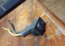
 Haha I definitely shouldn't touch wires anymore, I'm kicking myself in the ass lol