New LiFeBatt-based pack...

Jay, if you set your controller to 150A it will be fine with ap lifebatts. The controller will use full 150A for just a few seconds, mostly settling around the 100-120A mark I believe. In any case, you will be able to play with it and work out the best use when you have it running. Lifebatts start to warm up at around the 8-10C mark i've found, the voltage drop will be your key to how hard you are pushing them...


Ooops...^^ gary beat me to it and said the same thing:p I have tested the cells at these rates though, and they do OK (though nowhere near as good as the A123'S.)
 
bikeraider said:
Hi Gary,

Thank for this clue, but I have another question. I already have a 48 Volt 40 Ah duct tape pack for my dirt bike, the current limit presently on the Alltrax 4834 is set to 120 Ah (3C) or 40 %.

With a A123 pack at 48 volt 9.2 Ah, I can use this pack at 300 Ah. But I like to connect both packs in parallel for long trail riding. Theres away to do it, and to use a sort of protection on the duct tape pack to limit the curent at 80 Ah or less ?

Thank you for your help
Bikeraider

First of all, you set the controller current limit to A, not Ah, which is a measure of capacity. 3C is pretty high for duct tape packs, so you might be cutting the life expectancy a bit. To pull that much current from a duct tape pack, the BMS current limit would have to be 120A. I thought the limiters on these BMS boards cutout closer to 1.5-2C.

If you put a 16s4p a123 pack in parallel with the duct tape pack, it will certainly help, but by how much, I don't know. You still will have the same current limit issue with the BMS board on the duct tape pack.

-- Gary
 
Jay64 said:
Gary, I want to try to get some connectors that can plug straight into the ones on this pack. What are they called, where can I find some?

They are AMP 4.2mm PE Series plugs and receptacles. What you need is the 18-pin free-hanging plug and matching crimp sockets. The Mouser part numbers are 571-115880008 and 571-15863153, respectively.

-- Gary
 
bikeraider said:
Hi Gary,

There's no BMS on this duct tape pack, and I use an LVC for discharge. The output current is presently set at 40 %, your right about the Ping BMS but I don't use this stuff.

Great work on the new BMS, well design, have nice day!
Bikeraider

Right, I remember now...

If you are using the duct tape pack by itself, I would limit the controller to about 80A, which is 2C. With the 16s4p a123 "booster" pack, you can probably crank the current up to about 100-120A, but I'd keep an eye on the voltage drop. If it drops enough that the LVC circuits are tripping, that's too much.

-- Gary
 
Hey Bikeraider,

Not sure about the wiring viability of this... maybe a left thumb operated on-off-on switch?
(double pole /double throw) I think?
A123 pack (on) for accelerating, then throttle down, switch (off) then duct tape (on). Throttle
up again for cruizing. Probably wouldn't wan't to do much powered-up switching (big arc), but
could be a simple option??
Feel free to add / bash :D

K-ray
 
Hey Bikeraider,

Bikeraider said:
The most interesting and cheaper option I see for my bike. Is to buy some Headways cells 38120P those cell are 80 A continuous discharge and 160 A peak. With 60 volt and 56 Ah I think my dirt bike will be really fast and kicker.

That would definately work! Good luck with all the upgrades... nice ride 8)

K-ray
 
Ok, I've had some time to really look at the pack, charger and balancer, now I realize that I have a few more questions. I believe I got this pack, or at least one close to it.
16-Cell%20Pack-Charging-Balancing-a.jpg
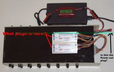
I just realized that I don't know what plugs into the balancers. I had assumed that you put the balancers between the charger and the battery to balance the charge. But looking at everything now, I see that you can't plug the charger into the balancer. Do you just plug in the balancers into the 18 pin connection like they are in the pic while the charger is plugged into it's corresponding connections and they just balance the cells while the charger is charging them?
I looked the part number up of the 18 pin connection up on mouser and it wasn't found. Howerver, I don't think I need that. That is the connection between the pack and the balancers, right?
In the picture above, I indicated what I think to be the power out wires. Is this correct? And if so, what type of plug is that so that I can connect to that plug? If not, which one is the power out connection?
 
Oh yeah, also, when I was reading the info on the battery charger, it states:
Caution:
Charge only gel, sealed or wet lead-acid rechargeable batteries.
Other type of batteries may burst causing personal injury and damage
do not expose to rain.

Is it ok to use this with the lifebatts?
 
Jay64 said:
Is it ok to use this with the lifebatts?
Alert! Alert!

Before you do anything you need to find out whether you somehow got the wrong charger. Beagle123 just destroyed $2000 worth of batteries (after using them for maybe 100 miles) because he made an error.

:arrow: This error could cost you a lot.

Before you go on you need to identify EXACTLY which charger you have in your possession and not what someone might have thought they sent you. You might have ordered the right thing and the guy on the other end screwed up.
 
Also to add..

You won't need to use the ballancer every time you charge, only once in a while if you let the pack sit idle for weeks type thing.

DO NOT leave the ballancer plugged in for extended periods of time when not on the charger !!!! :!: What it does is drain the higher voltage cells down to the lowest cell in the pack... using up some charge.
 
Yeah, I was told that I didn't need to use the balancer every time. I think something like every 5 charges or something like that. However, I am still exactly unsure of how to use the balancer. Does nothing get plugged into the back of the balancers? I just plug in the 18 pin connector while I am charging?

As far as the type of connectors that are on there. I found some Anderson PP connectors that look like the ones for the charger.
http://store.solar-electric.com/anpowpp180am.html
Do those really cost $15 a piece? :shock:
The other one looks similar, but both the wires go into one connector. I think that is the one I need to find. I want to be able to plug into that to get the power to my controller. Assuming that is the right set of wires for that.
 
I think the pp45 is the one for the charger.
10 sets for 99 cents sounds a lot better then $15 ea. :lol:
06-11-08_1323.jpg

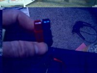
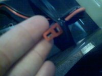
The one I am needing is this one. Is this the Dean?
06-11-08_1322.jpg
06-11-08_1324.jpg
06-11-08_1325.jpg
Sorry about the poor pic quality, I used my camera phone to save some time.
 
Sorry, I missed this...

Ypedal is right. The connectors on the other side are for using these with smaller battrey configurations. They aren't used here. The harness connects the balancers to each of the cell connections via the 18-pin connector on the front of the pack. The balancers work independently from the charger, so there's no direct connection.

The larger gauge wires, which ternminate in the Deans connector (These are used a lot in RC applications. I like them because they are small, but can handle 100A.) are the main pack discharge leads. The negative lead is routed through two 4110 FETs on the LVC board. The smaller gauge wires, with the PP connectors, are for the charger. The only difference is that the negative lead goes directly to the negative pack lead.

The charger works great for LiFePO4-based packs. It has adjustments for both voltage and current and what I did was max the current out at about 4.5A and adjusted the voltage so that the cutoff was about 59V, which works out to about 3.69V per cell.

It has been my experience that these LiFeBatt cells really don't get too far out-of-balance at all, but since you will be using them at higher current limits, I'd still use the balancers about every 5-6 cycles. What you want to do is plug the charger in, wait until the green LED comes on, which indicates it is in the final CV phase, where it drops the current to 1A and holds the voltage to 59V. You will see the current on the WattsUp meter start to slowly drop. When it gets down to 100mA, or so, you can turn off the charger and plug in the balancers and then go away for an hour, or so. Eventually, al the LEDs will blink in a randaom fashion, which means the cells are all pretty close. If you leave them connected long enough, all the LEDs will go off, which indicates that the cells are all within about .005V of each other, but I think this is overkill. Mainly, you just want to make sure the cells are all in the same ball park.

-- Gary
 
ypedal and Gary, thanks for clarifying that stuff for me. I have put in an order for some anderson pps and Deans. Are those anderson pps the 45amp ones?

also, how would this battery pack take to regen?
 
Are those anderson pps the 45amp ones?

also, how would this battery pack take to regen?
 
So just to get this straight. If I wanted complete protection of my cells I'd go with with LVC/Charge management/balancing in the form of the BMS, and then I'd just need the cells and charger. Right?

So for example 36V would be $360.00 for the cell's, $135.00 for the BMS, and $135.00 for the charger, for a total of $530.00 for 36V, right?
 
Jay64 said:
Are those anderson pps the 45amp ones?

also, how would this battery pack take to regen?

Yes, they are the 45A versions, but that is a continuous rating. I've pulled as much as 90A burst through these connectors, for brief periods.

-- Gary
 
Back
Top