New 'Mini Monster' Programmable Controllers Coming

I have a short question concerning the shunt in the 6FET controller
I have a 0.5mOhm SMD shunt lying around. Could I use this shunt to replace the original one in the 206 controller or would it be to low ?
How do I adapt the values for the Phase Current and rated current in the Designer program ?

Thank you very much

Thomas
 
bapou said:
I have a short question concerning the shunt in the 6FET controller
I have a 0.5mOhm SMD shunt lying around. Could I use this shunt to replace the original one in the 206 controller or would it be to low ?
How do I adapt the values for the Phase Current and rated current in the Designer program ?

Thank you very much

Thomas

The 0.5mOhm shunt should be alright. I think the original shunt was about 5mOhms, so you could scale the settings in the Parameter Designer by a factor of 10. I'm using a 1mOhm shunt I got from methods.
 
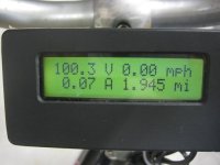
I finally have a new battery put together. This is a 24s, 5ah, 20C made from four Turnigy 6s packs. It's just over 100V hot off the charger.
100v.JPG

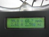
I did a no load test with a Crystalyte 5304 motor.
68mph.JPG

I need to get it all put back together and mounted on the bike, then I can take it for a spin :D
 
You can even use a 0.000250 (0.25 mOhm, 250uOhm) shunt.
Look to the 18 Fet thread for examples of software settings.

For my 300uOhm shunt setting the software to a given value gives me about 2X the current limit.
If I want 65A I set the software to about 30A DC and 80A phase, this gives me a 65A steady current limit.

All documented in the 18 fet thread.

-methods
 
stator said:
I finally have a new battery put together. This is a 24s, 5ah, 20C made from four Turnigy 6s packs. It's just over 100V hot off the charger.


I did a no load test with a Crystalyte 5304 motor.


I need to get it all put back together and mounted on the bike, then I can take it for a spin :D
What size of wheel? I am starting with the very same battery!
 
I run a 24S 5Ah pack on a 9x7 9C in a 26" rim.
If I set the current limit to 30A I can go 50mph and not overheat
Highly recommended setup :wink:

Just dont get greedy and turn the current limit up over 30A for 24S

An X5 will deplete the pack too quickly IMHO
Dont go too far from home :p

-methods

P.S. Bring a Y cable so that if you get close to LVC you can reconfigure the pack from 24S 1P to 12S 2P. This will get you home in a pinch if one cell hits LVC.
 
methods said:
I run a 24S 5Ah pack on a 9x7 9C in a 26" rim.
If I set the current limit to 30A I can go 50mph and not overheat
Highly recommended setup :wink:

Just dont get greedy and turn the current limit up over 30A for 24S

An X5 will deplete the pack too quickly IMHO
Dont go too far from home :p

-methods

P.S. Bring a Y cable so that if you get close to LVC you can reconfigure the pack from 24S 1P to 12S 2P. This will get you home in a pinch if one cell hits LVC.
Thanks methods. I do plan to double the pack very soon to 10ah maybe more. Just want to get up and running before I order more lipo not to mention it comes here quicker if you order 4 6s 5000mah packs at a time rather then the 8 you just ordered and got via slow boat! lol. Oh and my e-bike will have peddles still lol. Not to mention I will probably be giggling so much after ripping so far away I will have the energy to peddle for a while!
 
Hi methods,

thanks for your quick reply. However I think the factory shunt for the 18fet controller and the 6fet controller is different
(at least the photo for the 18fet shows 2 silver "shunts", and my 6fet has only one). Maybe I also missed some pages in the 18FET thread.

In theory the current values in the designer have to be scaled linearly with the resistance shunt values ? Than I will try to measure the original
shunt to get the right scaling.

Thanks
Thomas
 
That's a very interesting point about the shunts being different on different boards Bapou.
I wonder if that is why we have to tell Parameter Designer what board we have. Maybe the program tell the board what size shunt to expect.
If that were the case then in theory we could increase the max current limit by telling Parameter Designer that we have a smaller board than we really have.
That would also explain my recent experience where an unprogrammed board was more powerful than a programmed one, maybe it thought it was 6 or 12 fet board instead of an 18.
 
I went for a 5 mile ride. All flat ground. I thought I had solved the throttle cutting out problem, but it is still there. Other than that, there were no problems. The controller, motor, and battery stayed cool to the touch (I wasn't monitoring the temperature).

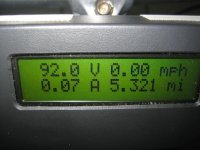
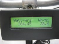
Voltage was just over 100V when I started the ride. This was at the end.
end_of_ride1.JPG

Less than half of the pack capacity was used.
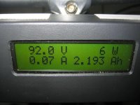
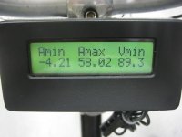
end_of_ride2.JPG

end_of_ride3.JPG

Wow! Over 5KW! I checked the shunt calibration before the ride.
end_of_ride4.JPG

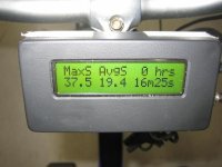
It was hard to go WOT very long due to turns. I was sitting upright the whole time. That's 60KPH. I'll try to go faster next time.
end_of_ride5.JPG

I'll be away this week, so no more experiments until next week :cry:
 
hi
stator what value are you using for the power resistor R1 it comes as stock with a 200 Ohm 2W resistor is this what you have in or have you changed it for a diffrent one?

Geoff
 
geoff57 said:
hi
stator what value are you using for the power resistor R1 it comes as stock with a 200 Ohm 2W resistor is this what you have in or have you changed it for a diffrent one?

Geoff

With this voltage it should be 1K, but I didn't have one, so I'm using 1.2K.

I also changed R11 to 19.6K. The shunt is .001 ohm.
 
Great to see some progress.

The 'Mini-Monster' has been mainly mythical at my end. My box of a dozen odd parts for 10 controllers is still lost in transit (and uninsured :cry:) Hopefully, it shows up sometime, somewhere and not in a picture on a ransom note from Somali pirates... I will split the loss/ransom money with methods despite his generous position of taking "full responsibility" as the sender.

Meanwhile, we continue undetered, infact, perversely, and perhaps recklessly, encouraged :mrgreen:: enough parts for 20 6-FET controllers this time are now on order including a sensorless version.
Ben


Mini-Monster controller development project casualty tally:
1 x 4110 MOSFET - dead
3 x Bosch Fatpack cells - dead
$600 parts box - Missing In Action
 
I love it!
Anyone know if this is what Kelly is using in their new mini controller?

-JD
 
He did not lose any money - just time.
Be patient. He has all the stuff he needs now.

-methods
 
I want to try a pair of sensorless mini-controllers.
 
I am building mini-controllers right now :twisted:

Replaced all (3) 63V electrolytic with 100V
Replaced 100ohm power shunt with 900 ohm (values seem off eh? This is an 846 from Justin)
added some 12awg to the traces

Stock it had 4110's and what looks like 14awg phase and power wires. I am leaving that.
Going to deliver it as an 72V 40A and hope the wires dont melt off :D

-methods

EDIT: I just changed my mind - I am going to run 750ohm on the power shunt. Stator - how did you calculate 1.2K?
 
Can these be run at 24Volts. I am working on a project that requires 24 volts and a max of 60 amps, continious 40 amps. Can this one do that? I really like the compact size of the 6 FET controller.
 
Depends on how low the LVC is. The controllers I have had the LVC set to 20V and used a 100 ohm 2W resistor.
Hypothetically - yes.
Anything over 13.25V should keep the regulator working

Performance is going to be sorry tho......

-methods

EDIT: You will have to spoof the ECU with the reverse mod that Stator etc. are doing. You would need to increase the lower leg of the divider to make the chip think that it is getting *more* voltage than it is. I could do this for you for the nominal price of $500. (or I can tell you how to do it for free :wink: )
 
Damn.... Blew up a 6 fet.
Miss-calculated the power resistors :oops:

I was trying to keep a real wide power range but hooked up 97V without thinking
The LM317 failed to a shorted condition. This caused the 5V regulator to bring the logic buss up to 9V
I replaced the LM317 and the 5V reg still works (5V) but I think the chip is toast
I have a replacement chip but I HATE surface mount work so I may or may not get around to it.

Anyway - for the record:
This was an 846
Original power resistor was 100 ohms (spec'ed for 36V packs - max of 60V)
I ran a pair of 680's in parallel for 340 ohms
Too low for 24S .... :twisted:

Now I have a pair of 1.8K's in parallel for 900 ohms.
That seems to work from 12S to 24S though I only tested it at 12S and 18S
Controller is meant for a 72V LiFePO4 pack

Set the current limit at 45A and at 66V it ran good.

Ok - Lets hear something about the mini-monsters...

-methods
 
Not even warm - but then it was 40F outside and I was going 34mph.

I did the chip swap - no dice :?

Dont know what else could have died. I guess all the 12V circuitry.

Whatever - parts bin :roll:

-methods
 
methods said:
I am building mini-controllers right now :twisted:

Stator - how did you calculate 1.2K?

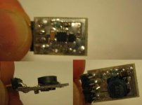
The maximum voltage drop the LM317 can handle is 40V. I think the minimum current is about 50mA. We want 12V output, so that leaves 48V to drop across the power resistor if the maximum battery voltage is 100V. That would require a 960 ohm resistor. I think I ended up using 1K. I'm changing out the LM317 for a switching regulator. I've built it, but have not installed it in the controller yet. It should work from 12V to 95V.

DC-DC_1.JPG
 
Back
Top