Bluesman
1 µW
Hi guys. Noob, first post. I have google:d and searched for 2 full days, but can´t seem to get info for the following.
Any pointers appreciated.
I got my first brand new e-bike just recently, and basically need just ONE improvement - to remove or alter the 25km/h speed limit. I´d like to have access to 30km/h.
Checking out my options wasn´t too easy. It´s a noname/rebranded e-bike setup (YOSEMITE=BILTEMA, Sweden. 250W/36V/10Ah . 3 step power control on handlebar.
28" 7 gears.
No idea yet what controller it has, its not labeled. I guess I will need to rip it out to see the PCB and pass the pictures here for advice.
This will be a big adventure, since the clever little folks assembled the controller and harness first, then the rest of the bike around it.
Anyway: I have TWO pieces of info so far. The motor i s a front hub marked BFSWXB 36V250W185R. This, to me, looks and sounds like a Bafang.
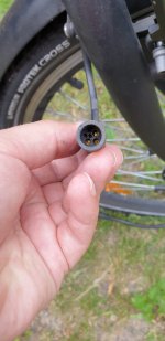
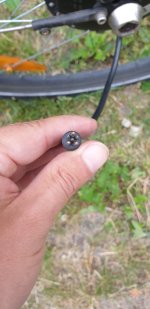
The motor connector is a 6-pin circular one. 3 thicker pins and 3 thinner. This looks like it´s a sensorless motor. (only 3 free pins available)
Hall sensors normally need 5 pins, I have read..
SO...3 thick pins=motor phases.
But..what are the rest for? Can I hope to keep it simple and get the speed limit disabled by fiddling with the remaining 3 pins only?


