Norco A-line 144v 200amp Lipo 150km/h build

You're actually a lucky guy. 207vdc taken across the heart is enough to pass your soul onto its next journey if your body takes the shock badly.
 
Glad to still be here... I was only touching the negative wire at the time, and I was wearing insulated gloves... but teaches me a serious lesson about doing dangerous things to distract from emotional distress; especially things that are only dangerous specifically when you are distracted... I will learn from this.
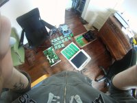
Also, I feel like I am truly lucky I didn't kill my computer; the hyperion was plugged into it via USB. I was hoping the charger was ok; upon internal inspection the two caps at the inputs were dead due to under rating for the voltage. I replaced them, took off the heatsink and checked the fets. I can't find anything specifically wrong with them, but the machine remains off. The board looks pristine, so I suspect death of the delicate chipset in some manner. Anyone have any idea what would logically happen when you plug too much voltage into a hyperion? What part would fry?
 
Glad to hear that you're OK. Matters of the heart dont mix well with voltage and current. Be safe!
 
Thanks man.

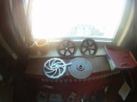
I just finished removing the wires from my second stator. When I redo the axle, if I take the wire out of the disk brake side I will have more room to play with in terms of an enlarged bearing hole then on the freewheel side; about 3cm diameter on the side with disk brake could be removed I think without compromising the structure that the disk is attacked too, whereas the other side would be left woefully thin if I were to enlarge the hole. I'd still rather do without an axle slot, even if that means running bundles of uninterrupted magnet wire out of the motor through multiple holes. We shall see if there is enough room.

RIP little buddy... I feel like I killed a pet. I loved this little thing...

deadhyperion.jpg

The hole with measurement

View attachment 1

And the two stripped stators

two stators.jpg
 
the connection you made was a total of 200V of batteries on the output? and it popped something inside?

there may be a diode, a zener across the output that blew up because it was overvolted, and the output may have caps that were overvolted, not familiar with the circuitry, but look for them, maybe it can be repaired.
 
Well, I just retested the fets, and all but one are showing source/gate conduction, so that means they are all dead i think. There is no obvious zener or anything; I don't think it has overvolt protection for 50s... There are two electrolytic caps over the input terminals, those blew, I replaced them.
 
Well charger shipped, and the kelly controller I wanted is still around! Expensive, but good!
 
Just sent the funds for my controller and contactor. The name of this thread basically just got confirmed :)
Dropped of my motor with my prof too; he is going to start on the lathe work for me. As I said, mid February for the wind...
 
Andje said:
Well, I just retested the fets, and all but one are showing source/gate conduction, so that means they are all dead i think. There is no obvious zener or anything; I don't think it has overvolt protection for 50s... There are two electrolytic caps over the input terminals, those blew, I replaced them.

Urk. That also means its gone through the drivers, and probably through the logic as well. Ouch.
 
yeah that's what i figure. I could poke around with my ttl/cmos probe but I can't really fix anything, it's all smd... I am still quite sad... I feel like it deserves a burial and a headstone... second in what will most likely become a line of small gutsy soldiers...
 
Prof suggested instead of building a mould and vacuum bagging fibreglass and such, to just fibreglass on balsa for anything not load bearing. I am investigating this.
 
Well, i ordered a bunch of thermistors and halls, and an arduino mega adk. I can eventually hook it up to an android phone via usb if i want! It is going to take a hell of a long time to learn C...
 
Arduino's version of C is not so bad. A lot of the ugly stuff is wrapped. I'm assuming from the Android part of the equation that you know Java - if you know Java you'll do fine with Arduino.
 
Bummer about you Hyperion, cheapest price I've seen is from this vendor $130. I picked up a spare one from him during Xmas.

http://www.ebay.com/itm/HYPERION-EOS-1420i-NET3-CHARGER-1S-14S-20A-MAX-550W-/300658636612?pt=Radio_Control_Parts_Accessories&hash=item4600a6b744#ht_1036wt_922
 
Um... holy shit. My Mouser stuff just arrived. I hadn't been aware I spent 15 bucks to expedite, but i can live with that for 24 hour shipping. Also, Arduino's are WAY smaller then i thought they were!
Now to get it working with EVERYTHING. Probably thermistor and halls first though. If i can get the thing inputting and outputting my hall signals than I can work on digital timing adjustment experiments too.
 
Adruino's are cool, I ordered one so I could build my own plastic quick prototyping machine. They use a subset of C language.
 
Yep, I got the basic analog to serial pwm output working and have the pot/led thing going. Im going to build the thermistor circuit and get that working to the led and then later get the code going to output to lcd in numbers.
 
I took the bike out for a ride yesterday, pedalled it 5 km or so, won't be doing that again; amazing cushy ride, but too springy to pedal efficiently and the chain guard obviously rubs the whole time and the rolling resistance of these tires is just silly. I can't WAIT till its electric, it will be an AMAZING ride.

In other news, my motor is in a tumbler with the idea of removing the remaining epoxy from between the stator slots. I was hoping to have it a week ago, but c'est la vie, beggars can't be choosers and such. I can't wait to get it back and start winding it.
I'm buying some more Makita packs, so I'll have another 240 cells to go through. If I am really going to go through the effort of moulding an external case from composite I want to make the pack last for a while and need a larger parallel then I have with my current 300~ cells.
Things are coming together, although it looks like I may have to make my own dropouts, Magudaman says he wont be ready until at least March or later... I fear a long project completion date. Unfortunately I think I can get them made by my prof pretty damn quick and for free -materials, so I may go with that option till I have more cash and there is a defined product to purchase. If I make my own I would assume I'd use steel plate and get my prof to mill them to the proper curves, then go with a pinch bolt style dropout as has become popular.
 
believe it or not I used to pedal mine about 10-20km every other day XC style. hard hard work but a good way to get fit.

yea making your own isn't that hard with access to a workshop. means you can make 'em to your exact own specs too (axle position/extension, pinch/enclosed). if you use 2 10mm plates you can bolt 'em together, makes it easier to make the recess for the 3 bolts that attach it to the rest of the bike.
 
So i bought another 240 makita cells. Starting to test them all now. I will probably eliminate anything not giving me 2500 ah and keep about 500 cells. I will aim for 42s11p I think. I have 328+~220 cells.
 
Well, after two rounds of Makita packs from Slycayer, I have some excellent results, and so far I can't thank him enough.
600 cells purchased, 1$ a cell
534 good cells
354 Grade A cells <3.0v
180 Grade B cells <2.5v

Discharge curves show a good average capacity of 2500mah+, with most of the A cells over 2750 discharged at 2c from 4.15 to 3.3 resting.
I will almost certainly shoot for a round number, and will probably go with 40s 12p to use 480 cells which allows me to discard 5 full packs of B cells that are low on capacity. I just stacked 8 of the 5s2p blocks together and it's freaking small. 6 of them will fit easily with some creative racking!

My controller is in the mail. My motor might be mine today; i have class at noon and will find out then.

ManyMakita's.jpg

with 480 18650V at about 50g apiece including the packaging and such, should be about 24kg of cells alone. Then I will probably end up with at least a kilo of wire and solder on that. So maybe 25 kilo battery. Good thing I only weigh 130 lbs soaking wet! Should end up with 2953 watt hours capable of about 27000 watts at 10c. That would be epic. It would probably give me peaks of more then that, but by 30kw there is all ready about 3000w of heat in the freaking motor lol... My controller is "rated" at 300 amps peak, but I will probably keep it at 200 for the sake of it's longevity.
 
I"m interested to see your building technique, with connecting the cells. From what I know, you need a tab welder to do it right.

Sounds like this bike will weigh about just as much as you :eek:
 
Tab welder would sure be nice; however, both DocBass and John in CR build packs of these with just soldering thick copper. I am going to follow johns advice and not clip all the cells apart; that way they start out as blocks of 5s2p and I can stack 8 together to make a 40s2p block with only 16 soldering joints between the + and-. 6 of those and ill have made only 96 soldering joints in total for my 40s12p.
Im confident that part of the project will come together, I am more concerned about how I will build the metal rack that will hold them. It has to be semi lightweight since the batt is already so heavy, but it can't be light duty since I plan on taking drops on this thing if I can. I am still investigating a full or mostly composite holding solution with maybe just metal reinforcing the very bottom at the attachment point. Might get heavy, might need carbon fibre to offset strength/weight.
I was working on my hall sensors to arduino code, it's coming along. Should be fairly easy to make it work, harder to understand how changing the timing digitally will effect the bike, but who cares, I will experiment.
 
did you stagger the magnetic phases on the hubs adjacent each other? will there be two sets of halls going to two controllers or does the controller control both stators with the same current? so then everything would be aligned, magnetic poles that is.
 
Yeah, they are aligned; one controller one set of halls, and the two stators are effectively one now. This is only two motors based upon the b its, once I am done I will have one double wide motor in all ways.
 
Back
Top