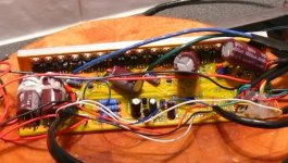
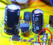
:oops: Fixed EB 218 Over volted now no 5volt

NeilP

1 GW
Joined
Nov 27, 2010
Messages
5,012
Location
49.17303, -2.05354 Jersey, Europe
Havve been running a test bike with a 24 series pack but with the batteries below full charge..98 volt..94 volt etc.

Charged the pack up just now, but let it go a bit far, to just over 100 volt...100.3

Plugged it in to controller, forgot the precharge, so the usual spark..and CA lights up...but controller no longer works.
Lights do not flick on on the cruise control and no response when moving the throttle...
Checked and the 5volt line is at 1.13 volts. so looks like the 100 volt has zapped something

LED comes on, on the controller...but other than that it does not work

So what is the fix? Voltage reg? have not even taken it apart yet..is this going to be an easy fix? what do you all reckon?
 
Trace the 1,3V back to regulator output and check any components for heating. It seems the regulator is smoked.
Remove/Isolate the regulator and try to use an independent 5V source to power the bus. Test if it works, then replace the regulator or any other damaged parts.
Before using it again, make sure to increase the R1 value.
Have you used a low resistance motor?
 
miuan said:
Before using it again, make sure to increase the R1 value.

OK, will look at that

miuan said:
Have you used a low resistance motor?

No idea. it is this one from an unknown e-bike.
But I do not think that has any bearing on this, have already done two or three miles on the bike built up on this wheel, at the lower voltage (24s pack but not charged up fully). It was only pluggin it in, wjhile it was turned on, and the resulting spark that I reckon casued the damage. it was all fine and doing 30mph, half an hour before

file.php

file.php
 
Any idea where the 12 volt coms from?
just thinikg of where to start trying to trace the 12 volt from...which component are directly connected to the 12v line?
 
dnmun said:
the 12V rail comes off the 12V regulator. the 5V regulator will be next to it on the pcb.


OK, cheers. it maybe obvious when I open it up to look, but if not, what is the 12 v reguator? what am i looking for ? a 3 pin package? an 8pin DIL IC

Cheers
 
Hi Neil,

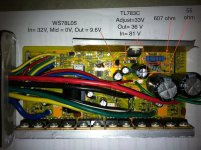
maybe i can help you out here, i had to trace the 5 and 12V rails on my infineon this summer. Below in the picture you can see:
- the big blue resistor 607 ohm is feeding the battery voltage
- onto the 12 V regulator TL783C (although it says 36 V , don't worry, it was my problem at that time)
- then the output of the 12V reg is fed into the 5 V reg WS78L05 (again, it says 9.6 but that was my problem, now solved)

hope this helps

front annotate.jpg
 
Depends; many controllers use a TO220 LM317 chip. Some use an SMT version, and some use a full switching regulator either off-board or on it's own section of the controller PCB.
 
Ok, thantks guys

i have looked at the pictures I have of the board, and it does not have a To22 style package, opposite the output FETS like Huges controller, but there are two transistor size three pin packages in a very similar place
.

I have not taken the controller off the bike yet, I zapped it but had to then rush off to work..Need to go and take it off the biek int eh morning and get it out for a bertter look. I only have partial pictures of the top of the board here at home
 
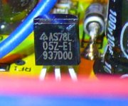
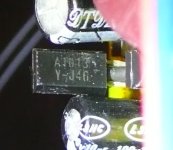
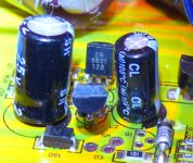
OK, here are some pics of the only devices that I can see that may be voltage regs

555 is transistor
AS78L seems to be a reg
Also a AS393M...surface mount comparator

No voltage on the board except battery voltage, 98 volts or so

P1120884.JPG

P1120885.JPG

P1120888.JPG
 

Attachments

  • P1120890.JPG
    P1120890.JPG
    127.3 KB · Views: 2,279
It is quite possible that you could have zapped the main processor(MCU).
Try to see if you can program the controller.

If you can't program it then most likely the controller is done for, unless you don't mind replacing the chip so that you can keep using the same FETS.

I had a similar situation and I initially thought that there was a problem with the transistors(2n5551, mpsa92) or voltage regulator, but it turned out that most of those components were fine.

My suggestion is to try programming it. Another thing you can do is to hook up an independent 5v source to see how it behaves.

Let us know what you find.
 
the p/n's on those are:
2n5551 (npn transistor 160v 600ma)
http://www.fairchildsemi.com/pf/2N/2N5551.html
78L05 (5v 100mA linear regulator)
http://www.national.com/pf/LM/LM78L05.html
a1013 (PNP Transistor 160v 500ma)
http://www.datasheetarchive.com/dl/Datasheets-24/DSA-476436.pdf
1n4744a (15V, 1W Zener Diode)
http://www.fairchildsemi.com/pf/1N/1N4744A.html
just guessing the pnp/npn and zener are used to regulate down to 12v (or 15v) and then the 7805 to get mcu/hall/etc power.

dunno what the first reg circuit is designed as though

if 98v stops at the blue power resistors with nothing on their other ends, they might be open.
 
RoadShear said:
It is quite possible that you could have zapped the main processor(MCU).
Try to see if you can program the controller.

Funny you should say that
But this controller can't be programmed, it is a Crystalyte one, and it won't program anyway. Went through all of that when I got it. Even spoke to Kenny at Crystalyte. The MCU has a paint spot on it, which apparently indicates it is a single flash only device

RoadShear said:
Another thing you can do is to hook up an independent 5v source to see how it behaves.

OK, thanks, that will be my next attack.. I will feed 5v in from the unused pedal sensor input, and see if it runs.
BUT...I measured no 12volt line anywhere on the board either...does anything use 12volt? or is it merely a step down to obtain 5volt? I have been told there is a 12v rail, but as I say, not detected 12v anywhere..or a second reg,I would have expected two regs..one for 12v one for 5? is that assumption correct?
 
the 12V is typically used to supply the drivers of the FET's... the FET's need at least 12V to turn them fully on.

Looking at the pictures, it would be a botch job but it should be possible to replace the controller chip with mine...
 
Have you also check continuity between pin 4 and pin 8 of the SMD 393 Comparator? These are VCC and Ground pins. If there is a short between them, then the comparator has also gone bad.

I believe the comparator is part of the voltage regulation circuitry as it determines the conductivity of those transistors.

What is the current when you power on the controller?
 
Well the MCU is OK

I fed the board 5v, 'backwards' up the 5v out on the pedal assist plug, and the controller then works.

It appears that the 5v regulator is working OK, because once the controller is On, and after feeding 5volts in from external source, the 5v reg circuit gets up and running, I can disconnect the 5v supply, and the controller runs fine.

If I power off, while monitoring the 5v line, I can power up the controller again, and as long as the 5v line voltage does not drop down below 2v olts or so, then it powers back up correctly with 5volt (well 4.96) on the 5 volt line.

So it seem what ever powers the 5 volt on has failed.

What would this be?
 
amberwolf said:
1n4744a (15V, 1W Zener Diode)
http://www.fairchildsemi.com/pf/1N/1N4744A.html

Where did you see that one? My eyes are not that bad, but I can't even see it on the actual board let alone the pictures!! :cry:

OK, so I have found the 5v regulator seems to be working..but needs to be kick started in to action with an external source above 2 or 3 volts. Otherwise the controller seems to work OK
3 speed switch, reverse, and power output all normal.

Am taking a wild guess here that we have a switching issue here.. maybe one of those transistors
Power is getting through to the reg to produce 5 volts, but it is not turning on because of no external 'stimulus'...but feed it 5volts the wrong way..up its input..it thinks it is supplying volts and therefore 'wakes up' and tries to regulate it.

So is it one of those transistors?

Or what..no idea what to try next, apart from random removing of components and replacement with new ones
 
why not study enuff to know what you are doing?

just swapping random parts is not efficient. keep studying until you know what a 12V regulator is and what they do and what they look like and then learn how to follow the traces so you can see where the current flows.

it takes time to learn stuff but then you have the basis for maintaining the system.
 
I know what you are saying, but that is not going to happen, Reasons why:

1) too busy doing other stuff, rebuilding a Harley, Landrover, and Dexta tractor,

2) Would love to, but never did understand enough electronics theory while at school, Left in 87 to go to Uni to study agriculture and agric engineering, and amateur radio stuff. Finally left the education system when I was 26..or maybe a bit more. Worked in Ag for a few years, then in 2000 gave that up and did three more years in aviation studies and went flying for a living. Am f** ing sick of study for a living..really can't stand the thought of doing it all over agin in yet another subject for pleasure. I was happy enough at school building electronics projects/ etching PCB's etc but never got the theory...am too old to want to start now. I will help people with what I know, in whatever subject, and there are other people like me that are willing to do the same with their skills.


If I pick things up as I go, great, but full on study just to fix the odd thing, no way, especially when there are others out there like myself, willing to share their knowledge.

I can follow traces, see a blown resistor/FET/Cap etc, but if it is not physically damaged, that is where the problems start
 
but you are the only one who can diagnose and fix it. it is not really possible for people who in most cases do not know anything either are giving you advice. that makes it impossible to figure out what is wrong. you have all the skills to learn it. it does take time, but you can teach yourself what you need as you need it and have the satisfaction of knowing you are learning skills that help you more than others. all jmho

learning to follow the traces to see what other components they contact forces you to go read the data sheets and wikipedia to see what the other parts do, you don't have to know circuits or be able to design electronic cuircits to do it.

if you have found the 5V regulator then the input to the 5V regulator comes from the 12V rail. so finding it and figuring out which leg of the 12V regulator is the output leg and which is the ground lets you see how the current gets there through the input resistors from Vcc.
 
Yes, i can see what you are saying..and there is no learning involved in following traces, that is just visual.
There is only one regulator on the board, that I can see, and even if there are two, a 12v and 5v, they both do work, it is just they do not fire up till v is applied externally.

There are a lot of other people who have already worked on these boards, so there is a chance that someone else has had similar problems with them, or at least can say what the issue is. Same way that we can often diagnose a phase wire short or similar.

I know there is no 5volt or 12volt anywhere on the board when it is dead, only 98 volt battery voltage

if I feed 5volt in from the output side, then the whole unit comes live.
Tomorrow I will try and do this with the board out the case again, and see if I can find 12volt lines too.
if what you say is correct, that the 5v reg is fed from 12volts, then I need to trace what turns on the 12 v reg...where ever that is...maybe it is a series of discrete components rather than a single reg...or maybe the only reg I can see is the 5v reg, and the 12v is produced from discrete components...zeners, transistors etc etc
 
Hi NeilP,

It is a good news that your MCU and 5V circuit are still functional.
The problem now should lie in the high voltage regulation circuitry.

Most boards use either LM317 voltage regulator (common in 12FET or 6FET models) or
SMD 393 comparator coupled with a PNP and NPN transistor (more efficient than LM317) to bring down the battery voltage to around 12-15V.

Since your board doesn't have LM317(being a 15 or 18FET controller), then your switching circuit consists of the SMD comparator with PNP and NPN transistors. To keep the theory short, the 393 comparator serves as an OP-AMP which forms a feedback loop that determines the conductivity of those transistors.

You may think of the switching transistor(A1013, PNP) as a control element in series with the input source. By changing the conductivity of this control element, a range of output voltage can be realized. Conductivity of this transistor is dependent on the voltage at its gate. The gate voltage of this transistor is controlled by the 2N5551(NPN), which varies according to the output of the comparator.
The zener diode serves as an extra voltage clamp. It is also used to bleed off extra current to relieve the stress on the transistors.

So the best bet is to check to see if these transistors and comparator work properly. Also inspect the voltage after each resistor as you trace down the line from the battery ignition node.
 
Hi Neil,

i don't know a lot about electronics, but to produce 12V (or in that range) from your 98V input one has to dissipate some heat.

My 12 V reg is attached to a rather large heat sink. From your picture it seems there is no other heat sink but the one for the FET.

Probably you checked, but..have you checked there is no other component than FET attached to this heat sink ?

Then, on my board, between the 12V reg on the main voltage in, there is one big blue resistor to sink the voltage a bit and dissipate heat. I see you have 3 similar big blue resistors. Could this serve as a primitive 12v reg ?

Just my 2 cents, or make it 1.5 cents...
 
NeilP said:
amberwolf said:
1n4744a (15V, 1W Zener Diode)
http://www.fairchildsemi.com/pf/1N/1N4744A.html

Where did you see that one? My eyes are not that bad, but I can't even see it on the actual board let alone the pictures!! :cry:
file-1.jpg
i just am used to spotting zeners in old linear psu stuff, esp when salvaging parts off dead units. so i already 'know' the rest of the p/n from the part i can actually see there. ;)

i don't think there is any smps on the controller as i don't see the necessarey inductoeres. i am not suer what the circuit is but i would guess the pnp/npn are setup to controll the batt-v down to the 12v or 15v that runs gate drive and is then dropped to the 5v reg.

but i think that the problem is higher upstream, at th e blue pwoer resistoers.
 
Back
Top