Open Sensorless BLDC controller

casainho said:
I can't understand the voltage and amps of your battery. And can you please tell me what voltage and current does your lab power supply do?

My lab power supply is 20V, 10A. My battery is a A123 M1 8s7p pack, so 28.8V max and 16Ah.see here for more details
 
Walls99, I ended the schematic (prototype V2) and the mainly difference from yours is the microcontroller and BEMF/Hall sensors :)
As you can see, I am using mostly the circuit you shared! Thank you for sharing.

 
r34,r36,r38 can go to the corresponding phase leads instead of the ground

and the VS pin of the ir2181's need to go to the phase connection too
 
nieles said:
r34,r36,r38 can go to the corresponding phase leads instead of the ground
Are you sure? could you please explain why? On Walls99 schematic that doesn't happen, I hope he can verify this.

nieles said:
and the VS pin of the ir2181's need to go to the phase connection too
Thanks!! Done.
 
casainho said:
nieles said:
r34,r36,r38 can go to the corresponding phase leads instead of the ground
Are you sure? could you please explain why? On Walls99 schematic that doesn't happen, I hope he can verify this.
Nieles is correct, they should go to the phase leads. They are gate discharge resistors and should be between the Gate and the Source of each FET. I never populated those, they are more of a safety in case your brain gets disconnected while your power stage is active.
 
the pull down resistor needs a return path to the source of the mosfet. for the high side fet this is not gnd.


edit: oops too late :lol:
 
walls99 said:
I never populated those, they are more of a safety in case your brain gets disconnected while your power stage is active.
How about at power up/down? Even thou the brain can powerup very quickly, couldn't a short shootthrough (maybe because you just turned stuff off and on again quickly, or by bad connection) happen? I always saw these weak turn offs as essential.
 
Njay said:
walls99 said:
I never populated those, they are more of a safety in case your brain gets disconnected while your power stage is active.
How about at power up/down? Even thou the brain can powerup very quickly, couldn't a short shootthrough (maybe because you just turned stuff off and on again quickly, or by bad connection) happen? I always saw these weak turn offs as essential.
I understand and agree. I didn't know where should I wire them (I don't understand very well the mosfets, I guess).

I am not sure the values for that resistors and the others from the drive to the gate. I put 10R because I believe they should be small, only to avoid "ringing"/really fast currents. Can anyone verify the value for those resistors? Thanks.

By the way, the schematic sources (on KiCAD) are here: https://github.com/casainho/EBike-Smart-Controller/
 
Njay said:
walls99 said:
I never populated those, they are more of a safety in case your brain gets disconnected while your power stage is active.
How about at power up/down? Even thou the brain can powerup very quickly, couldn't a short shootthrough (maybe because you just turned stuff off and on again quickly, or by bad connection) happen? I always saw these weak turn offs as essential.
In my setup the controller is always powered up, the brain goes into low power mode when not needed and the gate state is always under control. When the battery has to be disconnected/reconnected, I use an anti-spark resistor to slowly load the capacitor, so the brain comes up well before.
 
casainho said:
I am not sure the values for that resistors and the others from the drive to the gate. I put 10R because I believe they should be small, only to avoid "ringing"/really fast currents. Can anyone verify the value for those resistors? Thanks.
10 ohm is a good starting point, you will have to adjust this depending on how much ringing you get with your design. I ended using zero ohm resistors.
 
Walls99, do you have an updated schematic? I found that the one you shared misses some resistors values... even that "anti-spark" resistor. Your experience/work is very relevant for me.
 
casainho said:
Walls99, do you have an updated schematic? I found that the one you shared misses some resistors values... even that "anti-spark" resistor. Your experience/work is very relevant for me.

The anti spark resistor isn't there permanently. A suitable resistance slows the inrush current down to levels where there won't be any sparking (you slowly charge the capacitors).
 
walls99 said:
I had a quick test with the new sensor, ACS758ECB-200B​, the motor unloaded, a max phase current of 160A and it seemed to work. Next I will do more load testing and work out how to adjust the current dynamically to avoid burning the motor.

Good and bad day today, I have being able to confirm that with 160A phase current, repetitive acceleration and regen braking, I can warm-up my controller and trigger the temperature alarm currently set at a lowish 50C. Doubling the phase current also allowed me to confirm that my controller can handle 3KW peak.
Unfortunately the SK3 6374 motor didn't like that treatment too much and got quickly hot even with the sizeable radiator. More worryingly there is now something loose in the motor, so I'll have to take it out to find out more about the damage...
 
walls99 said:
It's a 100A MCB that I got from ebay here.
I bought a 10A and other 6A MCB on a local shop. The MCBs are for ~ 230V. None of them works with 10A of my lab power supply.

Do you have any suggestion? Maybe I am doing something wrong...
 
casainho said:
walls99 said:
It's a 100A MCB that I got from ebay here.
I bought a 10A and other 6A MCB on a local shop. The MCBs are for ~ 230V. None of them works with 10A of my lab power supply.

Do you have any suggestion? Maybe I am doing something wrong...

Try more current, the MCB rating is much lower than the tripping current, see http://en.wikipedia.org/wiki/Miniature_circuit_breaker#Standard_current_ratings
 
walls99 said:
More worryingly there is now something loose in the motor, so I'll have to take it out to find out more about the damage...
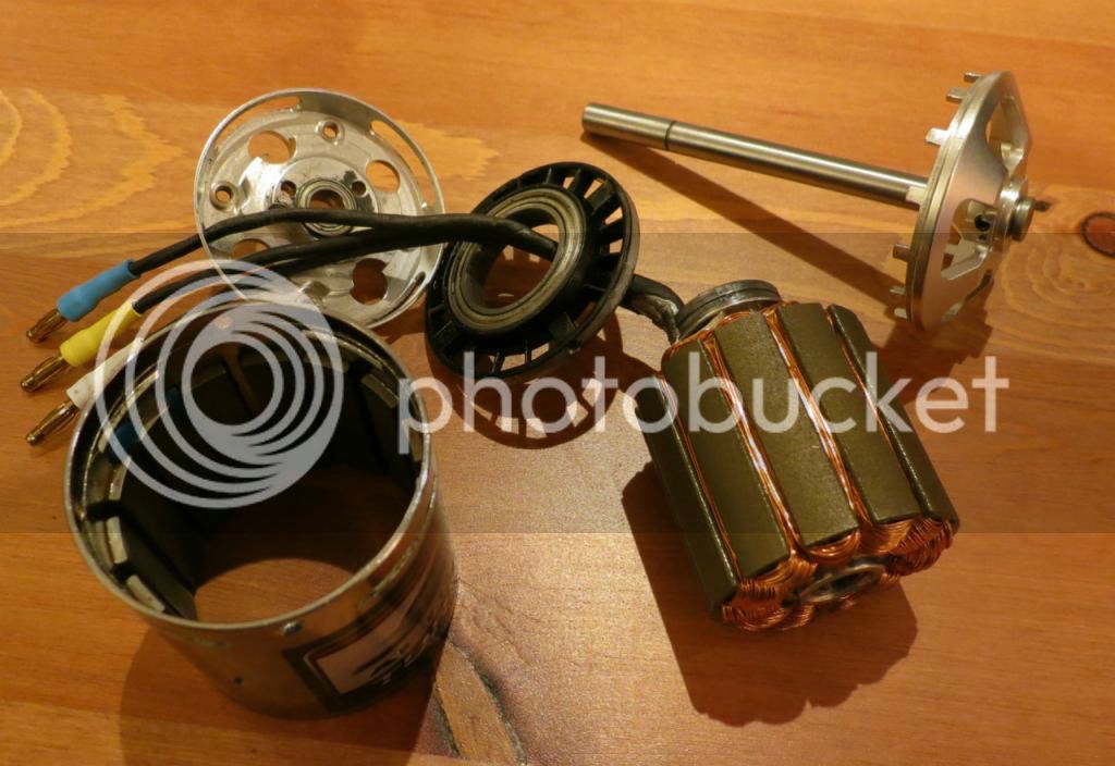
Ok, looks like a couple of screws came loose and 1 bearing is not in good shape. It's all back together but having seeing how small all the part are, it's clear this motor is not designed to handle the 3-4KW that I have being pushing through...

IMG_1681_zpsc641e76f_s_zpsf0ca7893.jpg
 
Hi Walls99.

I am building my prototype V2 and I got a problem with the mosfet drivers IR2181 (the same you use, right?). The LO signal is working great but the HO is always "high" at 9.5V while Vcc is 11.2V. The 9.5V of HO turns on the high side mosfets :-(
Maybe I am doing something wrong... all the 3 IR2181 behave the same way, with problem.

Can you please see the schematic I am using? there are some resistors that seems placed different on mosfets when comparing to your schematic.

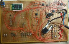
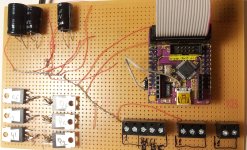
Here the pictures of my current prototype V2:
prototype_2-2012.12.24-01.jpg

prototype_2-2012.12.24-02.jpg
 
casainho said:
I am building my prototype V2 and I got a problem with the mosfet drivers IR2181 (the same you use, right?). The LO signal is working great but the HO is always "high" at 9.5V while Vcc is 11.2V. The 9.5V of HO turns on the high side mosfets :-(
HO is referenced to VS, so it's the voltage difference between VS and HO that matters. As long as HIN and LIN are low, HO-VS and LO-COM should be ~0V. Note that COM and motor GND should be connected. You should use the motor GND for everything than only connect the current sensor between the motor GND and the battery GND.
 
walls99 said:
casainho said:
I am building my prototype V2 and I got a problem with the mosfet drivers IR2181 (the same you use, right?). The LO signal is working great but the HO is always "high" at 9.5V while Vcc is 11.2V. The 9.5V of HO turns on the high side mosfets :-(
HO is referenced to VS, so it's the voltage difference between VS and HO that matters. As long as HIN and LIN are low, HO-VS and LO-COM should be ~0V.
Thanks!! I verified with the oscilloscope putting oscilloscope GND on VS pin and than I could see the signal!!

All were correct except that I missed the connection from each phase to VS pin. All works as expected now, thanks!!!

walls99 said:
Note that COM and motor GND should be connected. You should use the motor GND for everything than only connect the current sensor between the motor GND and the battery GND.
I am not doing that... after seeing your schematic a few times, I thought I were doing correct. Could you please explain a bit this?

Finally the motor starts and runs almost perfect. As I was thinking, looks like the prototype V1 (KU63 mosfet driver circuit) couldn't be drived correctly with 3.3V and so I could't start the motor by simple apply Duty_Cycle to the motor -- now it works!!!
But is not perfect yet, after about 75% duty_cycle the motor starts to make noise and asking more current... I need to verify if drivers are ok, etc.
 
casainho said:
am not doing that... after seeing your schematic a few times, I thought I were doing correct. Could you please explain a bit this?
It will probably work fine under low load but will start going bad when you increase the current, check the IR application notes about this, the FET driver COM signals need to be directly connected to the bottom FET source:
http://www.irf.com/technical-info/appnotes/an-978.pdf
http://www.irf.com/technical-info/appnotes/an-937.pdf

Since the current must be measured before the power capacitor, I connected one side of the current sensor to the controller/motor GND and the other to the power capacitor GND and battery GND. Under high current the motor/controller GND will be few 100mV above the battery GND, so the logic GND needs to be connected to controller/motor GND.
 
walls99 said:
Since the current must be measured before the power capacitor, I connected one side of the current sensor to the controller/motor GND and the other to the power capacitor GND and battery GND. Under high current the motor/controller GND will be few 100mV above the battery GND, so the logic GND needs to be connected to controller/motor GND.
Ok, I just did that, thanks. Here pictures and video: http://smartebike.likesyou.org/doku.php/prototype_2

1. Can I archive and make available for download your schematic/source files and your firmware assembly file? Because I plan to archive and make for download all the files for my prototype V2 which is almost equal to yours (mainly difference is the microcontroller, firmware in C and no BEMF circuit).

2. IR2181 have the "special" capacitor for driving the high side and this may be a limitation in some aspects. Do you have any suggestions for PWM being done on HI or LO side mosfets? How are you doing?

3. Your current control (ADC read processing) is done at which rate? does it have high priority (if using interrupts)?

4. I hope to soon start thinking on my prototype V3 which I plan to be a PCB. I am also thinking on 2 modules as you did and I would like to ask you the logic behind your 2 boards. I would to have a modular system, with possibilities for better mosfets/more power and different voltages. I am still to define the circuit parts that changes with this and the ones that keeps constant.

And my video recorded just now (25.12.2012):
[youtube]trihb86_mnw[/youtube]
There are some problems with high duty_cycle value... I see the power supply cutting the power...
 
casainho said:
1. Can I archive and make available for download your schematic/source files and your firmware assembly file? Because I plan to archive and make for download all the files for my prototype V2 which is almost equal to yours (mainly difference is the microcontroller, firmware in C and no BEMF circuit).
I have updated my controller schematics, the battery connections (UB) are clearly marked now. The source is available on demand for people interested but not ready for full release.View attachment Hoverboard_blmc_41.zip
casainho said:
2. IR2181 have the "special" capacitor for driving the high side and this may be a limitation in some aspects. Do you have any suggestions for PWM being done on HI or LO side mosfets? How are you doing?
Just make sure that your step period have a time limit to reload the bootstrap capacitor when the top FET needs to be always ON. For the PWM, I use use synchronous PWM for higher efficiency and regen capability.
casainho said:
3. Your current control (ADC read processing) is done at which rate? does it have high priority (if using interrupts)?
Every 50us, it's not the highest priority but it is handled in an interrupt.
casainho said:
4. I hope to soon start thinking on my prototype V3 which I plan to be a PCB. I am also thinking on 2 modules as you did and I would like to ask you the logic behind your 2 boards.
Compactness mainly
 
walls99 said:
casainho said:
1. Can I archive and make available for download your schematic/source files and your firmware assembly file? Because I plan to archive and make for download all the files for my prototype V2 which is almost equal to yours (mainly difference is the microcontroller, firmware in C and no BEMF circuit).
I have updated my controller schematics, the battery connections (UB) are clearly marked now. The source is available on demand for people interested but not ready for full release.
Thanks!! There are more information like resistor values on BEMF circuit that I would like to know.

I think now that I couldn't start the motor before (on prototype 1) with BEMF because problems of mosfet circuit drivers (3.3V weren't enough to drive the drivers). I may back to sensorless and maybe use your circuit ;)

walls99 said:
casainho said:
2. IR2181 have the "special" capacitor for driving the high side and this may be a limitation in some aspects. Do you have any suggestions for PWM being done on HI or LO side mosfets? How are you doing?
Just make sure that your step period have a time limit to reload the bootstrap capacitor when the top FET needs to be always ON. For the PWM, I use use synchronous PWM for higher efficiency and regen capability.
Hmmm, later I need to read more about "synchronous PWM for higher efficiency" and "regen capability". If you can, I will be able too ;)

walls99 said:
casainho said:
3. Your current control (ADC read processing) is done at which rate? does it have high priority (if using interrupts)?
Every 50us, it's not the highest priority but it is handled in an interrupt.
Good to know, I already made some tests also at 50us. But I am not sure it is working well... I want to go lower, to 10us. Right now my current control is on main loop and should be VERY quick but I need to use an interrupt for keep priority to this control, as I want to send data by UART to Bluetooth module and that will take a lot of time, it shouldn't block the current control.

My current problem is maybe due to demagnetization of the coils. I verified that, as seen at the end of the video, the lab power supply seems to cut the energy due to high current, but funny is that the voltage increases of the lab power supply!!! I never saw this happening but for sure is energy coming from the motor wingdings.

[youtube]trihb86_mnw[/youtube]
 
Walls99, what are the capacitors value you use at input of your controller??

I found that the problem I had were the "ringing" on commutation. I changed the resistors from 10R to 100R and got a better system but I ended up to change again to 470R. No I have no problem but rise/fall time is really bad, about 1us!
I wounder is there is a way to get quick rise/fall times but still avoid the ringing problem.
 
Back
Top