Open Sensorless BLDC controller

I have added a new feature to my controller to work out the remaining battery capacity using Coulomb Counting. This normally requires sampling the battery current and adding up the results but I found out in testing that approximating the battery current by the phase current time the PWM ratio what pretty good. The assembly code implementation was rather simple and fast too (12 instructions) which was important since this runs at PWM frequency.
I had estimated my C corrected battery capacity at about 16Ah and in my 1st test I measured 16.2Ah till the LVC kicked in and after 12Km in a city environment without regen.
Ironically enough, it's the displaying of the state of charge on my goped which only have 3 LED that took the longest to code (70 instructions) and debug...
 
casainho said:
patallen said:
thanks guys for the reply.

i found some bugs in my code that may explain why my proto P3 went south. will work that out and be more carefull on my next test.
So is your OpenSource your project? If so, please share the link as I would like to see/learn with it.

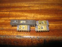
Hi, no its not my project. I dont feel smart enough to post my crapy code. I learned coding on my own 20 years ago with OTP pic 12c and 16c so its kinda very rough :oops: . I may do it someday, i would prefer end up making a open pcb design for such application. I am on my way to draw a proto pcb similar to the one on this project from Walls99.
 

Attachments

  • IMG_8162.JPG
    IMG_8162.JPG
    369.8 KB · Views: 3,774
walls99 said:
I have added a new feature to my controller to work out the remaining battery capacity using Coulomb Counting.
Having the remaining battery capacity is an important feature! Do you know other way instead Coulomb Counting?

walls99 said:
This normally requires sampling the battery current and adding up the results but I found out in testing that approximating the battery current by the phase current time the PWM ratio what pretty good.
Good to know.

walls99 said:
I had estimated my C corrected battery capacity at about 16Ah and in my 1st test I measured 16.2Ah till the LVC kicked in and after 12Km in a city environment without regen.
1. Does your remaining battery capacity works if you make small kms at a time, without charging?
2. Does your remaining battery capacity works if you make small charges at a time?

About free wheeling
I have one question: How to implement free wheeling?
Right now my controller free wheels when brakes are activated or when throttle is zero (if cruise control not active). I am thinking that when I get a down road I easily pass the motor max speed and I should put it on free wheel on that time, right?
 
casainho said:
Do you know other way instead Coulomb Counting?
no

casainho said:
Does your remaining battery capacity works if you make small kms at a time, without charging?
yes, the coulomb counter is only reset when the BMS indicates the charge is complete.

casainho said:
Does your remaining battery capacity works if you make small charges at a time?
no, this would require the BMS to also measure charge capacity and communicate it to the controller which is possible in principle but not really high priority for me, since I rarely use partial charge.

casainho said:
I have one question: How to implement free wheeling?
Right now my controller free wheels when brakes are activated or when throttle is zero (if cruise control not active). I am thinking that when I get a down road I easily pass the motor max speed and I should put it on free wheel on that time, right?
Unless you are prepare to add extra "switches" to totally disconnect the motor from the controller, I don't think you can avoid some current flowing back to the battery through the MOSFET diodes when the motor exceeds its max speed.
 
walls99 said:
casainho said:
Does your remaining battery capacity works if you make small charges at a time?
no, this would require the BMS to also measure charge capacity and communicate it to the controller which is possible in principle but not really high priority for me, since I rarely use partial charge.
Ok, thank you. Remaining battery capacity and estimated battery available kilometers for traveling are important features for me!!

walls99 said:
casainho said:
I have one question: How to implement free wheeling?
Right now my controller free wheels when brakes are activated or when throttle is zero (if cruise control not active). I am thinking that when I get a down road I easily pass the motor max speed and I should put it on free wheel on that time, right?
Unless you are prepare to add extra "switches" to totally disconnect the motor from the controller, I don't think you can avoid some current flowing back to the battery through the MOSFET diodes when the motor exceeds its max speed.
Ok. A more direct question: do you stop the 6 steps commutation after motor max speed (max speed for a specific PWM, current, etc)?
 
Hi Walls99.

Could you please tell me what kind of protections do you implement on your firmware to avoid burning the fets in case on some malfunction? for example, do to test motor stall?

Do you stop the 6 steps commutation after motor max speed (max speed for a specific PWM, current, etc)?

I am now looking to make my controller more robust as possible.
 
casainho said:
Hi Walls99.

Could you please tell me what kind of protections do you implement on your firmware to avoid burning the fets in case on some malfunction? for example, do to test motor stall?

Do you stop the 6 steps commutation after motor max speed (max speed for a specific PWM, current, etc)?

I am now looking to make my controller more robust as possible.

I check min/max battery voltage at ~1kHz and min/max phase current at ~20kHz. I don't test for max motor speed.
 
walls99 said:
I check min/max battery voltage at ~1kHz and min/max phase current at ~20kHz.
Hmmm, I thought you could be testing for wheel blocked also, like if wheel doesn't move for at least 1km/h during 5 seconds, disable the mosfets/motor. I understand that should be no big problem if wheel is blocked and the system keep providing the max current but maybe could be good to avoid that situation since seems it can mean an existing problem on real system/bicycle/bike.

walls99 said:
I don't test for max motor speed.
But that is because you have Regen working, right?
 
There is almost no difference if maximum current is being fed at speed or at stall. I don't see a point in shutting down after 5 seconds of stall, maybe exception of cheap chinese controllers. 1 minute stall allowance should be OK, because it can get annoying.
Also, whqt do you mean by "motor max speed" and why one should check it?
Is there a gap in your motor theory knowledge..?
 
circuit said:
There is almost no difference if maximum current is being fed at speed or at stall. I don't see a point in shutting down after 5 seconds of stall, maybe exception of cheap chinese controllers. 1 minute stall allowance should be OK, because it can get annoying.
I am thinking that in real application, like a bicycle or bike, the wheel should not be stopped or something wrong is happening, so, system should be shutdown/disable the motor/mosfets. But I got your point of view, thanks.

circuit said:
Also, whqt do you mean by "motor max speed" and why one should check it?
I mean when it stop to be motor and start to work as a generator. I think that mosfets should be off at that time, right?

circuit said:
Is there a gap in your motor theory knowledge..?
Yes :)
 
casainho said:
circuit said:
There is almost no difference if maximum current is being fed at speed or at stall. I don't see a point in shutting down after 5 seconds of stall, maybe exception of cheap chinese controllers. 1 minute stall allowance should be OK, because it can get annoying.
I am thinking that in real application, like a bicycle or bike, the wheel should not be stopped or something wrong is happening, so, system should be shutdown/disable the motor/mosfets. But I got your point of view, thanks.
What I was trying to say is... The motor actually does not care if it is spinning or not. If current is the same, it is getting the same amount of heat. The only difference is if cooling is somehow RPM-dependent (it has a fan, for example). For example it's almost the same for hub motors.

casainho said:
circuit said:
Also, whqt do you mean by "motor max speed" and why one should check it?
I mean when it stop to be motor and start to work as a generator. I think that mosfets should be off at that time, right?
Wrong. Motor/generator mode only depends on PWM duty cycle. Increase the duty and you will have a motor; decrease it and it's a generator. Algorithm is a bit different in cheap chinese crap, but theory behind them is the same.
 
circuit said:
Wrong. Motor/generator mode only depends on PWM duty cycle. Increase the duty and you will have a motor; decrease it and it's a generator. Algorithm is a bit different in cheap chinese crap, but theory behind them is the same.
Let's say my motor max velocity is 20km/h and that on a flat I can pedal up to 30km/h. I am with 100% duty-cycle and pedaling at 25km/h, now the motor is running as a generator, right?
 
casainho said:
circuit said:
Wrong. Motor/generator mode only depends on PWM duty cycle. Increase the duty and you will have a motor; decrease it and it's a generator. Algorithm is a bit different in cheap chinese crap, but theory behind them is the same.
Let's say my motor max velocity is 20km/h and that on a flat I can pedal up to 30km/h. I am with 100% duty-cycle and pedaling at 25km/h, now the motor is running as a generator, right?
If motor is above it's no-load speed at that same voltage, it will regenerate independently what you do with PWM. It will even if you power down the controller.
 
circuit said:
If motor is above it's no-load speed at that same voltage, it will regenerate independently what you do with PWM. It will even if you power down the controller.
Ok, and the best that can be done is to turn off pwm, right? (Or use some real switchs, no?)
 
I guess that if you keep spinning the motor faster and faster, with the MOSFETs off, there will be a point where the BEMF will be 2 diode drops above the battery voltage and the MOSFETs diodes will start conducting thus charging the battery. Then I guess that the regen current will start breaking the motor, and then I guess you could reach an equilibrium speed or just keep speeding up depending on how strong you're forcing the motor to spin up and up.
 
circuit said:
casainho said:
circuit said:
Also, whqt do you mean by "motor max speed" and why one should check it?
I mean when it stop to be motor and start to work as a generator. I think that mosfets should be off at that time, right?
Wrong. Motor/generator mode only depends on PWM duty cycle. Increase the duty and you will have a motor; decrease it and it's a generator. Algorithm is a bit different in cheap chinese crap, but theory behind them is the same.

Motor/generator mode depends on PWM duty cycle when synchronous rectification is used. Most RC/Ebike controller don't use that and I think they rely on changing the bridge configuration for the generator mode: Instead of turning the top side ON for one phase and PWM drive the bottom side on the other, they turn the bottom side ON for one phase and PWM drive the bottom side on the other. The regen strength increases as the PWM duty ratio increase and they still don't need to monitor the phase current direction because it has only on way to go is back to the battery through the top side diode.
 
Hi, question for the owner of this thread
how do you manage acceleration of the motor versus speed input ?
i mean, if the user slam dunk the speed to the maximum, do you allow the pwm to be increased up until it reaches a given maximum current, or you allow some sort of "ramping" of the pwm value ? Is the purpose of the PID in your code ?

I am playing with this on my home made controller.

Thanks.
 
patallen said:
Hi, question for the owner of this thread
how do you manage acceleration of the motor versus speed input ?
i mean, if the user slam dunk the speed to the maximum, do you allow the pwm to be increased up until it reaches a given maximum current, or you allow some sort of "ramping" of the pwm value ? Is the purpose of the PID in your code ?

In the version 1.x of my software, I used direct PWM control and a basic ramp function to slow down the PWM increase. The PID code was only used for the soft LVC. This simple PWM control approach works ok for RC toys but I would not recommend you use that in a high power controller.

I have sent you a pm with my latest code which implement torque control. The PWM is no longer set by the throttle but by a PI loop that controls the phase current. The throttle input is used to set the target phase current/torque with almost no filtering so the torque/throttle response time is instantaneous.
 
walls99 said:
patallen said:
Hi, question for the owner of this thread
how do you manage acceleration of the motor versus speed input ?
i mean, if the user slam dunk the speed to the maximum, do you allow the pwm to be increased up until it reaches a given maximum current, or you allow some sort of "ramping" of the pwm value ? Is the purpose of the PID in your code ?

In the version 1.x of my software, I used direct PWM control and a basic ramp function to slow down the PWM increase. The PID code was only used for the soft LVC. This simple PWM control approach works ok for RC toys but I would not recommend you use that in a high power controller.

I have sent you a pm with my latest code which implement torque control. The PWM is no longer set by the throttle but by a PI loop that controls the phase current. The throttle input is used to set the target phase current/torque with almost no filtering so the torque/throttle response time is instantaneous.


awesome. I knew there has to be somthing similar to what i am doing. Right now the ramp of the pwm/speed input request is much slower than my current measurements so i guess i am safe for now. My pic 16 has only 8 bit PWM accuracy so to reach 0-255 (full speed) it takes about 800msec. Motor inertia unloaded is jus thigh enough to achieve full rpm within that time. ACS measurements (x2) takes about 1msec, plus the math behind it to check thresholds.

On another note, you seem to have more than the casual programmer experience/knowledge. Ip, PID, windmill start-up and what else, plus tons of maths...This is not found and made this much clever with trial and error or by the weekender programmer....I would like to know how you reached this level of knowldge with BLDC motors and C/asm assembly programming. Thanks very much !!
 
patallen said:
On another note, you seem to have more than the casual programmer experience/knowledge. Ip, PID, windmill start-up and what else, plus tons of maths...This is not found and made this much clever with trial and error or by the weekender programmer....I would like to know how you reached this level of knowldge with BLDC motors and C/asm assembly programming. Thanks very much !!
Trust me, there has been many weekends and a lot of trial and error during the last ~5 years of development but I admit I didn't have to learn electronic/software for this project :)
 
walls99 said:
patallen said:
On another note, you seem to have more than the casual programmer experience/knowledge. Ip, PID, windmill start-up and what else, plus tons of maths...This is not found and made this much clever with trial and error or by the weekender programmer....I would like to know how you reached this level of knowldge with BLDC motors and C/asm assembly programming. Thanks very much !!
Trust me, there has been many weekends and a lot of trial and error during the last ~5 years of development but I admit I didn't have to learn electronic/software for this project :)


5 years...aouch !! and i am impatien because i didnt reached my goals within the last 5 month ive been working on that....doh !!
 
Hi Walls99,

I really liked your project and would like to implement it in an idea to control a car.
I have already purchased all the components for assembling the board.
Could you help me with the code modification?
My car will be controlled using signals RC. 1ms ~ <1.5ms -> 0-100% backward; >1.5ms ~ 2ms -> 0-100% forward.
Sorry writing, my english is quite bad.

thank you very much
 
Walls, can a turnigy servo tester be used as throttle on your controller and what do u use. I would like to build a bldc controller similar to yours and maybe use same source code but i am pretty new to the RC world.
 
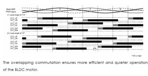
anyone would dare to comment this:
overlap method, from toshiba sensorless controller
shaded area shows overlap wich claims to make the circuit more efficient and less noise ??
i did try this chip and yes, it significantly reduces trapezoidal commutation noise. i am wondering how to implement this on a sensored controller such as mine. probably just a manipulation of the commutation table. :?:
 

Attachments

  • overlap.jpg
    overlap.jpg
    56.7 KB · Views: 1,125
Back
Top