open source UNIVERSAL quick swap battery

r3volved said:
Eclectic said:
2.5" drive are a great example of this. They went from spinning hard platters to all solid state without having to redesign the computers. As long as the "Black Box" (drive) manufacturers kept the form factors and I/O connections and protocols the same, it worked.
This is highly incorrect...go plug in a solid state hard drive into a windows 95 computer and then report back on how connections and protocols have not changed.
That's because the standards had been upgraded since Windows 95 to account for new technology. So your argument is that standards don't work if they are not backwards compatible to 20 year old technology even if they are compatible to 10-15 year old standards?

r3volved said:
Eclectic said:
Does it make sense to put the smart bits inside the the box? You bet'cha. Otherwise whenever the technology inside the box changes, you would have to change the interface to it. The idea is to keep the interface simple and standard.
This is also backwards...
You want your 'common/swap' parts as dumb as possible. THIS is how HDD's work...the brains are not in the HDD, the brains are in the PC in the form of driver commands to interface with the HDD's hardware.
Actually, if you look inside of a hard drive, there is smart stuff in there that generate the standard interface between the actual hardware and outside world. The outside world in this case is the hard drive controller. The hard drive controller then has another standard by which it communicates to the operating system. The operating system has another standard that it exposes to the software that runs on the computer. This is the reason that I can build a computer from standard modules and run standard software on it. The standards are always evolving and eventually get depreciated. But it all works because of standards.

r3volved said:
Eclectic said:
As far as voltage and capacity are concerned, I will go back to the hard drive example. It doesn't matter what the capacity or how fast the hard drive is as long as the drive controller can find those things out during the discovery process.
This is again incorrect in the application of batteries; you MUST increase the size of the container to increase the total number of cells. HDD manufactures have developed alternate methods to maintain form factor while increasing capacity...primarily through laser size.
And where would hard drive development be if every time that hard drives improved, you had to design a whole new computer to use it?

r3volved said:
A 'smart charger' should be able to interface with a 'smart bms' to establish capacity, chemistry, voltage limits and charge rates. The dumber the battery pack, the easier it is to 'hot swap' with a smart interface...like a computer does...
computer is smart - hardware is dumb

Absolutely... A 'smart charger' should be able to interface with a 'smart bms' but the BMS should know about and manage the battery. That way you don't have to reprogram and redesign the charging/controller systems every time there is a change in battery technology. By having the relatively inexpensive smart BMS manage the dumb hardware, the interface stays the same and you don't have to redo the entire infrastructure every time the technology changes.

I would assume that there might be a need for a couple of standard form factors required (like "AA", "C", "D" cells - those standards have lasted a long time). Standards always evolve over time and eventually become outdated but the modularity creates an environment that makes rapid development much easier.
 
flathill – I think your last iteration has merits. I think that 12VDC might make for a more versatile battery module.

The problems with current 18650s seem to be connection and management. Your design seems to address them.

For the sake of simplicity and economy, I could see eliminating any BMS communications. I would think that being able to determine a fault state would be beneficial as well as being able to set high and low voltage values. I would hope to be able to just push to or pull power from the module without worrying what’s inside (the BMS would take care of that).

I would caution against making the form factor specific to 18650s but maybe that is just the ver. 01 standard size.

Actually this has some of the attributes that I like about using Turnigy hardcases (like Chalo mentioned) because they give me a fairly rugged module with standard size, connectors, voltage that are easy to serial and parallel into a custom configuration. The downside to the hardcase is it has no management so I have to do that externally.

I realize that part of what you are doing is just brainstorming and hoping to get feedback here. It can be really frustrating because it can be very difficult to get a consensus on anything. I hope you have the fortitude to stick with it.
 
wb9k said:
We tested his first run print today. 100 Amps from a single cell is no problem. The cell gets warmer than the hardware. I think this looks very promising. My friend it pretty excited about this particular project, so I think I'll have more to report soon. The printed parts are OK for testing, but they're really not robust enough for the real world. Once the concept is proven with printed parts, he plans to have a mold made and parts produced by more conventional methods. Stay tuned!

Please do let us all know how this turns out (I think it deserves its own thread). There is a gap in the market for a modular system for weldless/solderless assembly of packs, particularly for the 18650 format.
 
Eclectic said:
I realize that part of what you are doing is just brainstorming and hoping to get feedback here. It can be really frustrating because it can be very difficult to get a consensus on anything. I hope you have the fortitude to stick with it.
This is an important point.
I refer to Roger Von Oech's 4 step method:
Creativity is not reliant on a brilliant flash of insight, a “Eureka!” moment where it seems the only sensible thing to do is run down the street naked. You can approach creativity systematically and one method is Roger von Oech’s ”4 Roles of Creativity.”

The Explorer’s job is to collect the raw material for creativity. He is constantly asking questions, talking to different people, and processing as many inputs as possible.
The Artist takes the raw material from the Explorer and combines it in new and interesting ways. He’s playful and imaginative with no concerns about judging the quality of what he’s creating.
The Judge takes the Artist’s ideas and determines if they’re practical. He thinks critically and realistically about what can actually be done.
Finally, the Warrior takes an idea the Judge has determined worthy and tenaciously follows it to completion. The Warrior’s job is to overcome resistance, be courageous, and ship the idea.

His book "A Whack on the Side of the Head: How You Can Be More Creative" can usually be found at the library and expands on the 4 role method. Reading the book changed the way I think in a fundamental way.
 
Eclectic said:
For the sake of simplicity and economy, I could see eliminating any BMS communications. I would think that being able to determine a fault state would be beneficial as well as being able to set high and low voltage values. I would hope to be able to just push to or pull power from the module without worrying what’s inside (the BMS would take care of that)

This is what I was thinking, BMS that fully controls charge and discharge limits and cell balancing. Yes, that's a sophisticated little board, but it's exactly the same in every module, so you get to amortize design and tooling over lots of units. It means the charger can be just as dumb as the load.
 
The problem is if you add an internal mosfet to disconnect the module when something goes wrong, like overdischarge, how to you enable the battery again without some sort of communication to either the vehicle (frame) or charger?

I guess I could add a reset switch on the BMS side endcap. In normal use the battery should never go wrong. I like the idea of not need a smart charger or master BMS controller.

I'm working on a modular solution now to enable 2s1p, 4s1p, up to 12s1p. One endcap will contain the BMS where the return bus bar is. The case is going to be an extrusion so it will be very cheap to make any length or you can just buy the 2s1p case and stack it up to 12s1p.

It will be totally not cost effective to make smaller than 6s1p packs but you can do it if you want. The first standard with be 6s1p. Note tesla modules are also 6s or 24VDC. We can use the same chips as they have on their 24V module BMS but make it much more compact :D

I have to put the cells end to end which is hard to do safely so I'm working on a venting system that blows out the BMS end of the pack. Laying the cells side by side is better for venting but the contacts AND bus bar volume goes way up. I like the stick form factor with the contacts on the end. I am abandoning the base plate cooling as there seems to be little interest and it makes the whole thing more costly/heavy.

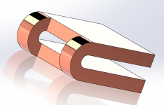
In between the end to end cells there will be a round silicone foam pad with a u shaped copper contact looped in on either side. The return bus bar on the BMS side will be where the mosfet will be located to cut the current flow.

The other endcap will contain the set of contacts that hook into the moving bus bar on the frame side, when the bus bar makes contact, the module is locked into place. This forms the main pack contactor also. I've decided the bus bar with clamp inwards as the actuation is much simpler/robust. The bus bars can be 1mm thick or 10mm thick :twisted: You will only need thick busbar if you are trying to parallel a thousand modules or whatever. For series use the nickel coated copper bus bar will be cut into sections (with a backing bar for support between sections) and the module mounting direction needs to be alternating.

The case will be a rectangle which seems like a waste but the wasted space will be used for the threaded rod, locating pin, and for venting. Air space is a very good way to prevent cell to cell thermal runaway.

I should have something mocked up in 3D by next week.

The form factor of old RC packs but made for 18650 and a zillion times better:

large__14_09_2010_07_49_NiMH_5000_7.2v_6cell_Shotgun_Pack.jpg
 
Hmm…seems to be getting similar to the Turnigy hardcases that so many of us here like to use. Nothing wrong with that. Solderless 18650 packs seem to be the hot topic on the forum right now and your current design addresses that.

T50004S-20HC[1].jpg
 
Yeah I'm thinking the first prototype will not have a BMS or any of that junk and will work exactly like the pictured hard case with some IP67 rated balance connector on the end cap.

I will just 3d print the frame for now and laser or hand cut the silicone gaskets. I want a single piece gasket made of silicone foam between each layer in the module to serve a dual function: to seal the whole thing up and to capture the u shaped contacts (spring loaded by the foam captured by the u shape). The exact same foam piece will also work to seal the end caps.

I am stealing the U-shaped contacts with a foam interlayer from NTS Works (creator of Zero Motorcycle in Santa Cruz) https://ntsworks.com/battery/mini-48v-battery/

I am stealing the air gap safety feature from BRD Motorcycles in San Francisco (aka faster faster or now Alta)

There will be two center threaded rods holding the complete 6s module together (so 3 layers and two endcaps). Between each layer the four corners will have dowel pins as locating features. They only need to be glued into one side. I could just use 6 threaded rods but it would be much heavier and would not locate the layers precisely unless they were only threaded on the ends (too expensive, I can get one meter of threaded rod for 5 buck retail). The dowel pins are a few pennies.

From there I will overcharge one cell in the middle of a pack and watch it vent (foil sticker on endcap with label information will blow off). A single cell fire should never spread to other cells. That is the goal for now along with making is super easy for anyone to assembly a kit. I may also try leave room to drill 4 corner holes so the whole module can be screwed down flat onto on a frame (such as the bottom of a skateboard). This will mean it can't be quick swapped but that is OK for some people. For large module arrays I would recommend a case mounted on the frame with slots for the modules to slide into.

Long term I will worry about the internal BMS and temp sensors and possibly adding a mosfet
 
Sounds like a cool idea. I think:

If your idea is to have "swapping stations" across the country, where you trade in your 48V pack for another charged 48V pack of equal capacity, there some considerations:

1) Who is doing the charging? Where is the electricity coming form? I can't just allow myself to make it across the entire country on everyone else's electricity without contributing any charged cells myself. That is a big concern I think, and is why only corporate-backed electric car technologies (ie. Tesla) are able to succeed in that respect.

2) The battery packs would need to be standardized, which means if I wanted to homegrow my own battery packs, I should have to send them out to a battery pack tester/certifier to have them labeled as "OK" if they're going to take part in the swapping.

Maybe an alternative is an ebike with "solar wings" which have solar panels on them and are conformed to a special design which will allow you some form of lift (to lighten your own power requirements while riding), and also affixed with solar panels to charge an extra battery while you ride. Sounds cool eh? :-D
 
here is the rough concept....

You can either use 2mm threaded rod or 2mm locating pins

You can use it for a standard flat pack if you want. Each cell has it's own modular case.

Built in the 6s1p config you would glue the pack together to seal it and then slide in the cells with the silicone discs that capture the spring contact

The silicone foam acts like a spring

Also note the u_shaped terminal narrows where it folds back. This is the fusible link.

The silicone foam willl have a fiberglass core fore easy assembly (no flopping around) and make it safe (cell to cell thermal runaway)

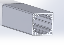
The fins that hold the cell in place also form 12 conduits for the up to 12 balance cables to run through and stay separated when you stack up to 12 cells end to end. These 12 conduits also serve as vents and as a thermal air gap (air is a good insulator) to prevent cell to cell thermal runaway going sideways. You can build as many in parallel as you want. The end cap will hold it all together and you can also glue the inner sidewalls if you want (likely not necessary). Only the ends of each cell holder need to be glued to weatherproof the module. The cell holder is an extrusion which is why it has not fancy features. The endcaps can be injection molded with features for a o-ring type gasket so the endcaps are serviceable/removeable. I didn't want to add gaskets in the inner layers between holders as they would squeeze out and prevent the cell from being slick and slide able into frame mounts and whatnot. Machined grooves for o-rings post extrusion will be too expensive. These should be pennies to make.

Note two corners on the cell case are chopped off. This is so you can make a groove to serve as a KEY to for proper orientation of a pack into the frame so you don't blow things up. Like I said these holders could also just be used on a flat sheet typical of other solderless packs you have seen built on here, but would be much safer. In this flat pack config you might want to use baseplate cooling. A different terminal will be designed.

I'm using 1/32" copper sheet for the terminal. You push it thru the silicone cutout then then bend it into a U-shape. The terminal is then captured with a foam inter layer. Right now I have it spec'd for 2.37mm thick foam with a fiberglass core. Figure it compresses again by half between the contact.

single_cell_holder.PNG
fused_U_terminal.PNG
View attachment 1
 
This is looking pretty good....evolving nicely. Many similarities to what my colleague has been coming up with for the 26650. I imagine you plan to make holders for parallel cell groups that can then be configured in series to build a pack? Whatever plastic you use, make sure it has low flammability. ABS is a good choice, and it can be printed :wink: .
 
how is it similar exactly?

to parallel the cells in the a flat pack the 2 case side plates should be lined with bus bar (laser cut copper sheet laminated to polyimide film

I thought about a side to side puzzle interlock feature but decided against it

you just need two plates to form a flat pack and then seal
the sides with foil tape (venting/safety/watertight)

the two plates are tied together with 2mm screws (you dont need 4 per cell)

thread one side plate

countersink the other side plate
 
Back
Top