Paralleling batteries of different Ah?

The Fusin battery still works. It's a well constructed battery with a key switch and a fuse inside a steel box. I have over a thousand miles on it. The problem is major voltage sag. It's not uncommon to see it sag below 48v until it finally cuts out at 44v. Any hill above 6% has me switching down to med. speed with the three speed switch. Any steeper and I'm down to low speed and peddling. I've been noticing a drop in amp hours till finally the other day at 7.1 amp hours it left me peddling home. Hot off the charger it reads 53.4v. But it doesn't take long to settle at 50v when under use. The Ping doesn't have this problem at all. Is it as simple as a not enough c rating?. When I tested the individual cells they were all the same. My voltmeter is messed up so I can't give exact numbers till it's fixed. Here's a pic. of it. I have the battrey out of the case and will post pics. of that this evening. Thank you for everyones input about the diodes. I was going to open another thread about this battery but since you asked...
 

Attachments

  • l_ad2f6d150fdb4071952dd6caa0783c45.jpg
    59.6 KB · Views: 710
  • l_efdc234a1e2744de839ad9859f5bb42d.jpg
    75.8 KB · Views: 706
Here's what the pack looks like out of the box...
 

Attachments

  • l_99e6579ce1d640be958e43f80906fd14.jpg
    45.1 KB · Views: 696
  • m_38a18d4ffda645139d05eabaf9564adb.jpg
    5.8 KB · Views: 694
what is the voltage out of the charger on to the battery at the end of the charge? can you measure each cell voltage and record it from 1 to 16 from low to high?

do you use one charger for this battery and another for the ping? what is the final output voltage on that charger?
 
Shortly after I received my Ping battery the charger for the Fusin battery went bad. Rather than return it to Steve I ordered the LiFePo4 specific Soneill charger from Electicrider. I charged the Fusin battery in the mean time with the Ping charger. The Soneill I tested before my voltmeter went bad. The voltage output is 58.7. The Ping charger was 60.1. Also I tested the cells at the B.M.S(thank you Dogman for telling me how) and came up with 3.5 volts each almost exactly across the board. Except this was when I started to suspect the voltmeter. Now it reads 5.5 exactly at every cell which I know is wrong but they seem to be the same. Something I noticed about the Soneill is that it only makes the lights on the Ping b.m.s go on for a brief second where as the Ping charger lights them all up and then they cycle down until I assume the cells are balanced. So I've been alternating, every fifth time I charge with the Soneill I use the Ping once. I'll try to get a new voltmeter soon but we(North Georgia) had some pretty major flooding and it's been alot of cleanup. Washed out my brand new asphalt driveway and the cinderblock wall I built to prevent such a thing. Wow Mother Nature sure is tough.
EDIT: Isn't a diode basically like a check valve? So at worst by adding the diode I might lose some power, at best it will protect the battery. Keep in mind I'm kinda new to this.
 
Crash Machine said:
Isn't a diode basically like a check valve? So at worst by adding the diode I might lose some power, at best it will protect the battery.

Crash Machine,

That's a good analogy. It does no harm, unless you want regenerative braking.

With a Schottky diode the power loss is small. At 10 A it will waste roughly 10 W as heat. This is a few percent of the total power but it means that you need some form of heatsink to stop the diode overheating.

At 10 A the ideal diode will waste well under 1 W.

Nick
 
If I have two LiFePO4 batteries that are exactly the same voltage and AH and each has a BMS from the same manufacturer, do I still need a diode if I use a Y cable to put them in parallel???

Secondly can I charge them a the same time using my Y cable? or do I need to charge them separately? We are talking about 2 x 24V 10AH LiFePO4 packs with BMS.
 
wildnrg said:
If I have two LiFePO4 batteries that are exactly the same voltage and AH and each has a BMS from the same manufacturer, do I still need a diode if I use a Y cable to put them in parallel???

Secondly can I charge them a the same time using my Y cable? or do I need to charge them separately? We are talking about 2 x 24V 10AH LiFePO4 packs with BMS.

Be a little bit careful here, we really need to know details of the BMS.

If they are always the same state of charge, then there won't be cross currents and they can be connected in parallel for charging or discharging. But you need to be careful that connecting in parallel for charging doesn't compromise the end of charge operations of the BMS.

You should also disconnect the discharge Y cable when charging.

Nick
 
Crash Machine said:
Shortly after I received my Ping battery the charger for the Fusin battery went bad. Rather than return it to Steve I ordered the LiFePo4 specific Soneill charger from Electicrider. I charged the Fusin battery in the mean time with the Ping charger. The Soneill I tested before my voltmeter went bad. The voltage output is 58.7. The Ping charger was 60.1. Also I tested the cells at the B.M.S(thank you Dogman for telling me how) and came up with 3.5 volts each almost exactly across the board. Except this was when I started to suspect the voltmeter. Now it reads 5.5 exactly at every cell which I know is wrong but they seem to be the same. Something I noticed about the Soneill is that it only makes the lights on the Ping b.m.s go on for a brief second where as the Ping charger lights them all up and then they cycle down until I assume the cells are balanced. So I've been alternating, every fifth time I charge with the Soneill I use the Ping once. I'll try to get a new voltmeter soon but we(North Georgia) had some pretty major flooding and it's been alot of cleanup. Washed out my brand new asphalt driveway and the cinderblock wall I built to prevent such a thing. Wow Mother Nature sure is tough.
EDIT: Isn't a diode basically like a check valve? So at worst by adding the diode I might lose some power, at best it will protect the battery. Keep in mind I'm kinda new to this.

That was absolutely my point, the doide can possibly help and will most likely only waste a small amount of energy. But you may not need it.

Also, 5.5 volts on any lithium based cell is DANGEROUS so I would check that voltmeter soon just to be safe:D
 
Tiberius said:
wildnrg said:
connecting in parallel for charging doesn't compromise the end of charge operations of the BMS.

You should also disconnect the discharge Y cable when charging.

Nick

Nick is exactly right, I forgot about that. I have been manually terminating charge and I forgot this point. The EOC condition is a current condition which is dependent on the amount of cells in parallel so.... what Nick said disconnect before charging...sorry!
 
Thanks

So you're saying:

1. OK to connect in parallel using a Y cable to use the battery.
2. Its NOT OK to charge in parallel, separate the battery packs and change individually.
 
wildnrg said:
Thanks

So you're saying:

1. OK to connect in parallel using a Y cable to use the battery.
2. Its NOT OK to charge in parallel, separate the battery packs and change individually.

I'm assuming here that the packs have 3 wires each:
Positive
Load Negative
Charger Negative

I'm also assuming the charger is a CC/CV power supply and each pack has a fairly standard BMS.

You should only connect the Positive and Load Negative in parallel without diodes if they are the same type of battery and same state of charge. So really you have to charge them in parallel as well to be sure of that.

When you charge in parallel you must make sure that the Load Negative wires are disconnected.

Please, don't take that as gospel, because I don't know the wiring of your battery or the circuit of your particular BMS. You should really check your particular case. Whenever I charge packs in parallel I disconnect them completely from the machine and use isolating diodes.

PS. Don't charge NiCds or NiMH packs in parallel unless you really know what you're doing. We're talking here about Lithium packs with BMS.

PPS. If you're not sure, don't do it. Treat the battery pack with respect, not just because it costs a lot of money - its also like a little bomb. Its got significant stored energy and nasty chemicals inside.

Nick
 
i parallel connected two ping packs both V2 48V 12Ah. i did this for about 3 months and i raced tiberious with this configuration at presteign. i didn't use diodes. i had seperate charger ports so the negative charge wires were seperate. i parallel connected the output negatives and positives. the secondary battery was charged, down its discharge wires, by the primary battery, which was being charged.

i read on here that the ping cells stayed ballanced really well and i figured that if i alternate which pack i plug the charger into then both packs will stay balanced. if both packs stay ballanced then no cells will fail. if they are together all the time then there will never be cross currents. i wasn't really carefull with my packs -i have had fuses blow, i have tripped the BMS's, etc, but both batteries still work fine. the ping packs seem really resiliant. i've not noticed any capacity fade but i've never looked. now my build has changed and i only have room for one pack, so i've put the other on a different bike. i'm not saying that its a flawless method but i can't see a senario where damage could occur? perhaps if a cell died in one pack then the other pack would overcharge the first pack. but i can't really see this being a likely or dangerous senario.
 
what monster just said is an example of what you should not do.

if you charge the two batteries, and they are in parallel without a diode between them to isolate them, then you have to disconnect the two batteries at the bottom while they are charging. you have to charge each battery through their respective charging port on their own BMS or you can damage the batteries.

you can use the same charger and feed both batteries at the top from the red charging wire and connect both batteries to the charging negative wire through the blue charging wire from the BMS, but the negative battery lead connection that allows the batteries to be in parallel has to be open while charging. this is important.

if the batteries do charge up to different potentials, then when you finish charging and reconnect the negative terminals of the battery, then the current flowing from the higher voltage battery can cause the lower potential battery to be damaged if the highest cell in the lower voltage pack was already up to 3.9V by pushing the voltage on that cell higher .

this is separate from the reason isolation diodes are used to protect a pack from over discharging into a dead pack, but it could be used as the reason for isolating the packs with a diode at the top.

if the packs charge to the same voltage, that should not be a problem. if they don't charge to the same potential and they are identical and using the same charger, you need to figure out why it doesn't balance.
 
Both my charge and dischage cables go to the same connection on the BMS, my cables are 2 x red and 2 x black, no third cable.

It looks like the only difference between the charge and discharge cables is the discharge cables are thicker. I've put anderson connectors on both now and I just use the discharge cable to charge and discharge the battery.
 
wildnrg said:
Both my charge and dischage cables go to the same connection on the BMS, my cables are 2 x red and 2 x black, no third cable.

It looks like the only difference between the charge and discharge cables is the discharge cables are thicker. I've put anderson connectors on both now and I just use the discharge cable to charge and discharge the battery.

Hi wildnrg,

We'd really need to know more about the BMS functions on those particular packs. There may be an end of charge cut off function that gets bypassed if you charge it that way. Did you get a manual or datasheet with the pack?

Nick
 
Tiberius said:
We'd really need to know more about the BMS functions on those particular packs.

Nick

You and me both, no instructions, no diagrams, no pictures, nothing came with my ebike conversion kit. What I do know is there are two terminals (+ and -) on the BMS and both the charge and discharge cables go to them. I know that when the battery is full the buzzer in the BMS goes off, and the external charger that provides 24-29V light goes from charge to standby. So the BMS must do something because the charge stops charging.

When the battery gets low, I hear the buzzer going off again, I have not run the battery to a stage where the output power has been cut by the BMS.
 
wildnrg said:
Tiberius said:
We'd really need to know more about the BMS functions on those particular packs.

Nick

You and me both, no instructions, no diagrams, no pictures, nothing came with my ebike conversion kit. What I do know is there are two terminals (+ and -) on the BMS and both the charge and discharge cables go to them. I know that when the battery is full the buzzer in the BMS goes off, and the external charger that provides 24-29V light goes from charge to standby. So the BMS must do something because the charge stops charging.

When the battery gets low, I hear the buzzer going off again, I have not run the battery to a stage where the output power has been cut by the BMS.

Interesting, so...

The extra cables are really redundant, and you won't be bypassing the BMS by charging them that way.
The BMS presumable cuts off the charge current, that's what the charger is reacting to.
If the BMS has a LVC function, which is most likely, then it must be able to cut off current in both directions.

You probably could parallel them up without diodes, provided you kept them together for both charge and discharge. In fact if you want charge and discharge on the same cable, then you can't use diodes. There might be a problem if one BMS failed, but that's a problem anyway.

Nick
 
Well here is a new twist.

My second battery that I ordered from the same company arrived this afternoon, even though the voltage and capacity are the same, and the cells are the same, it comes with a physically bigger BMS, and on this one there are 3 wires. A pair of wires for discharging and a pair of wires for charging and from what I can see a they go to different points on the BMS and battery pack and there is some 3 wire connection in the middle.
IMG_0057.jpg


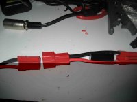
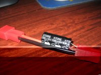
Also on the discharge cable is an extension cable with a3300uF 35V capacitor, which I don't have a clue what its there for, anyone have an idea what the capacity is there for??
IMG_0058.jpg
IMG_0055.jpg
 
If you are putting identical batteries in parallel and they are charged in parallel then no you don't need diodes, for example I have three 36V Bosch tool batteries wired in parallel. It is wise however to add Schottky diodes to the output of each pack if the battery packs are not matched for voltage, if they are different chemistries or if they have a BMS.

Practically it is difficult to ensure 2 different packs has a voltage difference less than 0.5v, so a diode might be a better choice, I don't understand technology, the diode acts as a fuse?

Oh yeah, I think many would like to know how the Fusin batteries perform
:oops: Crash's response make us recheck the controller cutoff voltage. The 48v cutoff voltage was set up 42V + - 0.5V, while battery BMS was set to cut off battery output at 40v (while it could actually work at 38V). So in his case it was actually the controller cut off the system, while battery could still work.

We have fixed this by set up the controller cut off voltage at 38v, while battery BMS keeps cutoff voltage of 40V. I know there are many professionals here, how you will think this new setting or is there a better one?

Response to us about products problem is absolutely welcome, this is main source of our quality improvements. Thanks friends :D .
 
Tiberius said:
Did it come with a new charger, or are you hoping to use the old charger on both packs?

Nick

At the moment I'm using the new charger to charge each pack individually. That's not a big deal as they at both the same capacity, the new charger is 5A the old is 2A.

I'm just a little concern that there is a capacitor wired up on an extension cable on the battery to motor cable. I've cut the cable and put anderson powerpoles on there and don't know what to do with the capacitor.
 
why do you think its a capacitor? do you have picture or can you describe it and read the stuff printed on it?

i did not mean to dis monster yesterday, just the charging of the battery through the single BMS. the other BMS was not able to protectt he cells under its control while the other BMS managed the charge.

in his case, i would have recommended using split leads from his charger, plugged into both BMS so they charged at the same rate, to the same voltage.

the trick is when one BMS is shutting down the charging FET to regulate the current can push more current into the adjacent pack, without the BMS being able to prevent an individual cell from over charging. that is what i meant by what you have to avoid. not that his parallel wiring of the packs without an isolation diode. that i approve of and think is the safest way.

but you guys already know what i think. diodes for different chemistries. or nicads in parallel (but i don't even use diodes in my paralleled nicads).

but if you wanna use diodes, go look at tiberius's thread on his FET based diode IC. that is worth the price of admission. share out a FET order and do that rather than installing little glow plugs inside your packs. they get hot. maybe he will talk about why it works here since so many are interested in the principal behind the idea of using isolation diodes. before pings name was used in vain. sorry ping.

maybe everyone can calculate the power loss in their own diodes, and look at the heatsink and maybe we can get temperature measurements reflecting various states of thermal isolation inside a cordura bag with the BMS and controller.
 
Crash's response make us recheck the controller cutoff voltage. The 48v cutoff voltage was set up 42V + - 0.5V, while battery BMS was set to cut off battery output at 40v (while it could actually work at 38V). So in his case it was actually the controller cut off the system, while battery could still work.
Actually the cutoff is 44v. My voltage rarely goes below 40v. So it seems that would be a better voltage for cutoff. I'm no expert.
Seems human error may have been at fault for why the capacity is dropping off on the Fusin battery. When I had the charger problem I took the top off the battery so I could monitor the voltage going into the battery. Upon further inspection of the battery I found a b.m.s wire virtually severed. Seems when I put the lid back on I pinched the wire. I know this is a dumb question but could that be my problem? I'm going to fix it and put it all together soon. Mystery solved. Up until this problem this battery would get the expected 10 amp hours at about 20 miles. Like Louis said cutoff was too high. Now back to our regularly scheduled programming
I'm still getting the Ping 48v 15Ah battery. The V2.5 has seperate wires for charging and discharging also. And it looks like they run into the Signal lab b.m.s. I expect the two packs will have a similar voltage so I'll see when it gets here. I don't like the idea of extra heat even though my power demands are low. I'll look into yhose FETs based diode you're talking about. No heat involved?
 
did you measure the voltages on the individula cells? if the sense wire was broken it would have trouble balancing. but with a broken sense wire it should not have worked at all in discharge with the v1 signalab BMS on it.
 
Back
Top