bobc
10 kW
When I built a new workshop, I though I'd try to go partially off grid with it.
I bought 5 125W panels from Bimble solar (UK) for about £300. They're not particularly efficient so they're quite big.
I mounted them on a south facing wall, so they will work better in winter - that makes sense for their intended use, a roof mounting would make more sense if I wanted max power to get infeed tarriff.
I have 6x 35Ahr leisure batteries connected. Lighting in the shop uses 10 x 1m LED strips - this is really good actually
I have "cigar lighter sockets" in a couple of corners for powering laptops (& any other 12V stuff), I bought 2 laptop PSUs for use in a car from ebay, they were just £5 each.
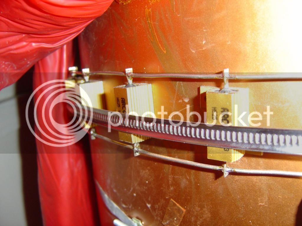
The battery charging control is a shunt regulator with a difference; when the battery is full (say 13.4V) excess charge is dissipated in power resistors that I have clamped to my hot water tank. 400 to 500W for a few hours on a sunny day gets the tank to a nice temperature for taking a shower.
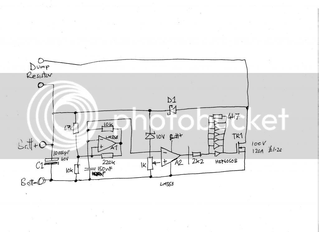
I thought I'd share the regulator circuit - it's pretty simple & seems to be looking after the batteries OK.
It basically uses a dul op-amp; one is used to generate a small sawtooth waveform, the other compares the battery voltage with the sawtooth to generate a PWM which goes from 0% at 13.2V to 100% at 13.7V (there's a pot to adjust the level)
A monster FET is driven by the PWM to power the 0.3ohm resistor round the tank (actually made of 30 1ohm resistors held on with a "duct clamp, essentially a big jubilee clip)
A big fat capacitor is placed across the battery connection near the circuit to avoid large AC battery currents and prevent consequent big battery voltage swings - that would probably be bad for the batts and interfere with circuit operation.
First attempt with the op-amp driving the FET gate directly was not so good and soon killed the FETs. This was because the LM358 has a slow output slew rate and is not so good for driving the big capacitance of the MOSFET gate - I was actually seeing gate risetimes of 40us so the switching losses were atrocious.

I'll post the circuit diagram shortly for anyone who wants to recreate....
2nd attempt, I used all the buffers in a 4050 CMOS buffer chip as a gate driver. This got the risetime down to 10us and the FETs much cooler. No FET death was caused by this circuit.....
3rd attempt, I used 2 resistors to put hysteresis/positive feedback in the gate drive buffer. This reduced risetime to 4us and guaranteed a 10us minimum pulse width onto the gate. THat will do!
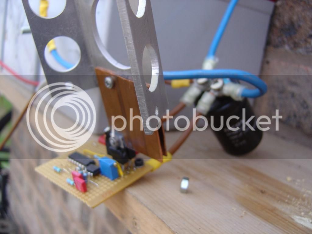
To heatsink the FETs and create the high current contact, I flattened some bits of copper pipe. In the end I also clamped a lump of scrap aluminium to them as well - the circuit is sitting in a hot place & I need to minimise delta T
Here are a couple of photos
I bought 5 125W panels from Bimble solar (UK) for about £300. They're not particularly efficient so they're quite big.
I mounted them on a south facing wall, so they will work better in winter - that makes sense for their intended use, a roof mounting would make more sense if I wanted max power to get infeed tarriff.
I have 6x 35Ahr leisure batteries connected. Lighting in the shop uses 10 x 1m LED strips - this is really good actually
I have "cigar lighter sockets" in a couple of corners for powering laptops (& any other 12V stuff), I bought 2 laptop PSUs for use in a car from ebay, they were just £5 each.
The battery charging control is a shunt regulator with a difference; when the battery is full (say 13.4V) excess charge is dissipated in power resistors that I have clamped to my hot water tank. 400 to 500W for a few hours on a sunny day gets the tank to a nice temperature for taking a shower.
I thought I'd share the regulator circuit - it's pretty simple & seems to be looking after the batteries OK.
It basically uses a dul op-amp; one is used to generate a small sawtooth waveform, the other compares the battery voltage with the sawtooth to generate a PWM which goes from 0% at 13.2V to 100% at 13.7V (there's a pot to adjust the level)
A monster FET is driven by the PWM to power the 0.3ohm resistor round the tank (actually made of 30 1ohm resistors held on with a "duct clamp, essentially a big jubilee clip)
A big fat capacitor is placed across the battery connection near the circuit to avoid large AC battery currents and prevent consequent big battery voltage swings - that would probably be bad for the batts and interfere with circuit operation.
First attempt with the op-amp driving the FET gate directly was not so good and soon killed the FETs. This was because the LM358 has a slow output slew rate and is not so good for driving the big capacitance of the MOSFET gate - I was actually seeing gate risetimes of 40us so the switching losses were atrocious.
I'll post the circuit diagram shortly for anyone who wants to recreate....
2nd attempt, I used all the buffers in a 4050 CMOS buffer chip as a gate driver. This got the risetime down to 10us and the FETs much cooler. No FET death was caused by this circuit.....
3rd attempt, I used 2 resistors to put hysteresis/positive feedback in the gate drive buffer. This reduced risetime to 4us and guaranteed a 10us minimum pulse width onto the gate. THat will do!
To heatsink the FETs and create the high current contact, I flattened some bits of copper pipe. In the end I also clamped a lump of scrap aluminium to them as well - the circuit is sitting in a hot place & I need to minimise delta T
Here are a couple of photos
")