Poor man's 15 Amp battery charger?

heathyoung said:
Are you using electrolytics? They don't do ac well unless you run them back to back (ie as a bipolar cap)


They are a bipolar "motor run" cap, which are actually designed to be used in a current limiting application on ac induction motors.
 
OK< long time since I looked at this thread..and this time I have nto read all the pages...but just updatuign this with some info regardign the schematic on page one..reproduced below

I'd jsut liek to say that the relationship of micro farads and charge current is not so straightforward as the diagram shows.

With a 300 microFarad cap, I get anywhere from 8 amps when charging a 20series(80 volt) 3 parllel pack ...to 24 amps when charging a 4series 1 parallel (16 volt) single pack.

Current is higher with a lower voltage pack.


http://users.telenet.be/a101944/batterij/Cheap%20charger.jpg
 

Attachments

  • Cheap charger.jpg
    Cheap charger.jpg
    17.5 KB · Views: 2,773
NeilP said:
OK< long time since I looked at this thread..and this time I have nto read all the pages...but just updatuign this with some info regardign the schematic on page one..reproduced below

I'd jsut liek to say that the relationship of micro farads and charge current is not so straightforward as the diagram shows.

With a 300 microFarad cap, I get anywhere from 8 amps when charging a 20series(80 volt) 3 parllel pack ...to 24 amps when charging a 4series 1 parallel (16 volt) single pack.

Current is higher with a lower voltage pack.


http://users.telenet.be/a101944/batterij/Cheap%20charger.jpg

Yeh I'm interested in reviving this thread towards making a better charger, putting in more protection and stabilizing components and getting better understanding of the operation.

Looks as if with your parallel pack you pull more current so drop more voltage in the circuit, capacitor/diodes,reducing charge current.
Would good to see a circuit simulation and work out a way to stabilize the current/ voltage output.
With the input I was thinking off protecting against overvoltage transients with TVS/MOV and overcurrent/short circuit a close rated MCB.
2014-09-02 08.14.00.png
Then the output voltage/current stabilization needs looking at.
Might be a way of having the input capable of delivery a high current value and creating the controls on the output low voltage side.
 
My issue at the moment is trying to find a capacitor, that is a run cap, not just a start cap, that does not leak its magic smoke within a few minutes, for a reasonable price.

Already cooked two or three caps that claimed to be good run caps...but only cost £4-5. I see plenty for sale at much higher prices...£70-80.


So for me the first issue is finding a reliable cap at a reasonable price
 
NeilP said:
My issue at the moment is trying to find a capacitor, that is a run cap, not just a start cap, that does not leak its magic smoke within a few minutes, for a reasonable price.

Already cooked two or three caps that claimed to be good run caps...but only cost £4-5. I see plenty for sale at much higher prices...£70-80.


So for me the first issue is finding a reliable cap at a reasonable price

I've been using these to charge everyday for two years now without any problems:
http://stores.directhvacsupply.com/80-mfd-440v-run-capacitor/
 
NeilP said:
My issue at the moment is trying to find a capacitor, that is a run cap, not just a start cap, that does not leak its magic smoke within a few minutes, for a reasonable price.

Already cooked two or three caps that claimed to be good run caps...but only cost £4-5. I see plenty for sale at much higher prices...£70-80.


So for me the first issue is finding a reliable cap at a reasonable price
Have you tried the back to back electr'o's heath suggested earlier?
Scrap a computer psu and salvage some.
Disclaimer on all this though read up and wear glasses, ear protect, make sure your caps are well discharged, test, I've only blew up small electr'o's big cans might go off :shock:
 
No, not started soldering lots together. Starts becoming a pain in the arts to build..i know it is not much, but just a little bit more to add to the to do list..but do have boxes of PC PSU's.
 
NeilP said:
No, not started soldering lots together. Starts becoming a pain in the arts to build..i know it is not much, but just a little bit more to add to the to do list..but do have boxes of PC PSU's.
Some supplies have 2 big value suckers on the bus, if your lucky.
Got 2x old rooted, HP server psu with 2 nice 450V, 270uF,
Could series/ parallel them for same value at 900V, unless we try a 3ph BB :shock:
 
Thinking now over moving over to a dimming circuit to bring up the p.f somewhat, to get a higher current from the outlet, as I'm after 3 to 4 kW charging.
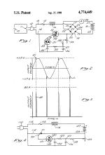
Found a patent for a simple triac charger, with some simple modern additions like the breaker for close circuit protection, MOV and filters on the mains side.
An oversized bridge rectifier fits where the load normally is and big caps on the dc side and tvs or zener to tame big spikes.
US4774449-1.png
images.jpeg
Any thoughts appreciated
 
I say bad idea.

You will most probably break the fuses or you will be using just a fraction of the wave where the voltage is just right. That doesn't help the power factor at all.

There are two solutions, you either use the already mentioned capacitor limited current build with higher input voltage or use a switching power supply.
 
Triac light dimmers are pretty cheap and would allow you to vary the average current, but I think the peak current would be destructively high. Once the triac turns on, it stays fully on until the voltage crosses zero. Even if the fuse didn't blow, I think the peak current would be pretty hard on the batteries. One could possilbly work with a run capacitor in series to limit the current. The dimmer would then allow you to turn it down.
 
Skippic said:
I say bad idea.
You will most probably break the fuses or you will be using just a fraction of the wave where the voltage is just right. That doesn't help the power factor at all.
There are two solutions, you either use the already mentioned capacitor limited current build with higher input voltage or use a switching power supply.

Best using a circuit breaker for these mains powered circuits, common and really cheap anyways a fuse can be more of a liability.
The Triac is effectively pwm, switching on the mains frequency, the bad boy cap limits by reactance, this effectively causes phase shift and poor p.f. not really an issue till you pull the big kW and mum is cooking or washing, then watch it.
:wink:

fechter said:
Triac light dimmers are pretty cheap and would allow you to vary the average current, but I think the peak current would be destructively high. Once the triac turns on, it stays fully on until the voltage crosses zero. Even if the fuse didn't blow, I think the peak current would be pretty hard on the batteries. One could possilbly work with a run capacitor in series to limit the current. The dimmer would then allow you to turn it down.
Yes, but that series cap would still be large and defeats the object somewhat of making the charger smaller and cheap.
Would'nt a control pot, turned down, on start up, still limit the output current value right down, as the voltage waveform should be cut early in and the connected depleted battery should effectively buffer and smooth and average current, waveform 4 below.
8cAge.jpg
The other thing theses devices should give, is controlability of the gate via bms, cellog output cetra.
 
fechter said:
Triac light dimmers are pretty cheap and would allow you to vary the average current, but I think the peak current would be destructively high. Once the triac turns on, it stays fully on until the voltage crosses zero. Even if the fuse didn't blow, I think the peak current would be pretty hard on the batteries. One could possilbly work with a run capacitor in series to limit the current. The dimmer would then allow you to turn it down.
Yeh your right, without producing a transition through zero, there's no chance of switching the triac off, not good, with the run capacitor is it possible, for size weight,, to have back to back electr'o's with bypass diodes across each, to protect the back voltage across them?

I still like the idea of a variable supply, like this
efficient+transformerless+power+supply+circuit.png
 
megacycle said:
with the run capacitor is it possible, for size weight,, to have back to back electr'o's with bypass diodes across each, to protect the back voltage across them?

Back-to-back electolytics as shown will behave like an AC capacitor. I think the problem is ripple current and how much heat is dissipated by the caps. With 10-20 amps I think most electrolytics will just blow up. AC run caps are designed to minimize the heating and are physically large enough to dissipate quite a bit of heat.

I have heard of people doing it though, so it might work if you pick the right caps.
 
fechter said:
Back-to-back electolytics as shown will behave like an AC capacitor. I think the problem is ripple current and how much heat is dissipated by the caps. With 10-20 amps I think most electrolytics will just blow up.
AC run caps are designed to minimize the heating and are physically large enough to dissipate quite a bit of heat.

I have heard of people doing it though, so it might work if you pick the right caps.
I was thinking of using surplus computer power supply electr'o's for now.
Might give it a go today, have a few about, boil some electrolyte and put on the full body condom :mrgreen:
My in line 10A circuit breaker will trip fairly fast, just make sure I stand back.
You mentioned the triac will get time to switch off with a series cap, can you enlarge on how that works?
 
If the Triac is before the bridge rectifier, the voltage will still swing through zero even with a capacitor in series with the line.

If you try the electrolytics, heating is the thing to look out for. Try it for a few seconds, kill the power, then feel the caps to see if they got warm. If not, then try for a longer time and repeat. If they never get warm, it should be OK.
 
fechter said:
If the Triac is before the bridge rectifier, the voltage will still swing through zero even with a capacitor in series with the line.

If you try the electrolytics, heating is the thing to look out for. Try it for a few seconds, kill the power, then feel the caps to see if they got warm. If not, then try for a longer time and repeat. If they never get warm, it should be OK.
Thanks, that's a really good thinking, i'll give it a go.
I tried the large value electro's with series diodes a shown, a few times for a few minutes each, feeding heat gun settings at around 1.4A, cool, 5A, warm, 11A cooking, they were psu 85deg, yep definitely need those oil filled mothers at big amps.
35A bridge rec was hot at 11.5A too
 
Yes, the bridge is going to get pretty hot no matter what. If you use a triac, it will dissipate a similar amount of heat. It might be a good idea to use a small fan to keep everything cool, including the caps. This way you can build it much more compact.
 
fechter said:
Yes, the bridge is going to get pretty hot no matter what. If you use a triac, it will dissipate a similar amount of heat. It might be a good idea to use a small fan to keep everything cool, including the caps. This way you can build it much more compact.

Cheers for that and reminding me I need to heatsink this lot together too.
Put a toroid choke in-line to the breaker, for in-rush, replacing the cap as in the patent diagram.
Just getting around to finalizing the gate resistors fixed and variable values.
Pretty fine movement on the pot, (only single turn) at present.
When it triggers on, it's over too much already
If it all works ok, be good if the circuit could be redesigned for finished, with external triggers.
 
I've been able to get to work using two phases of the wheel, for inductance, in the battery circuit.
With the basic gate circuit, the trigger point is very fine though and it kept on pulling over 30A from the 240V outlet, tripping the breaker in a few seconds
This would be flogging the battery too @ 6 or 7C.

Probably need better control over the triac, waveform and trailing edge maybe as shown previously.
 
Back
Top