ga2500ev, you should check your PMs.
I drew all this a couple days ago, then got busy (and also got sick), so I didn't post till now.
And keep in mind that I'm trying to design for 'everyone', not just myself, so would like it to work with 12 to 150V. I know this is a long post, but I tried to be concise, so please be patient while reading it.
First, I mentioned using a crowbar on the output earlier, but some might not know what it is, or how it would be implemented. The idea is to
absolutely disconnect the battery from the charger. (Think of throwing a metal bar across a set of power leads.)
I haven't worked with SCRs for decades, or done any research, so left the interface as a box with a ? mark for now.

The user interface (main) processor would send a 'watchdog' signal every 100ms or whatever, and if the crowbar interface doesn't see it, or if it's not the expected format, it will drop the crowbar. The user interface could also send a max over voltage spec to the crowbar processor, so it could sense over voltage and drop, but if the main processor was in an unintentional loop, it could possibly sent the wrong voltage (not absolutely foolproof), but in that case it probably wouldn't send the 'watchdog' signal. The zener could be replaced with an LM431. The over voltage portion of circuit wouldn't do any good if the processor is programed for too high a voltage either.

Next is the circuit I'm considering for putting a serial number ID on each battery. (Not having to program the charger every time you plug in a battery is part of making the system fool proof. If the user doesn't want this feature, leave it off!) The charger would then be programed with the charging parameters for that ID #. If said parameters change, as with removing a bad cell, all you would have to do would be to change the parameters stored in the charger.
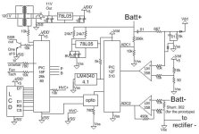
Starting from the upper left corner and going clockwise I will try and describe what I am trying to do, and why I chose the components.
The 900M resistor would supply current, and would be different for different voltage ranges. The processor would sleep around 98% of the time for low current consumption (<100uA). The circuit with the 100k resistor is used to detect charge pulses, and their timing so we can transmit at a low noise point (wake on rise). The next circuit would ideally convert the 150khz square wave output of the processor to a sine wave superimposed on the Batt+. The diodes would be to absorb spikes during connect and disconnect. The resistors with the T are thermistors for measuring batt temps. They are the reason for the processor choice. The touch sensor inputs make resistance measurements easy (they put an accurate current source out, then measure the voltage). I would hope it's obvious why we want battery temperature sensors.
For the signal I'm thinking of a pulsed 150khz tone. By defining a 0 as no pulse followed by it's mirror image, and a 1 as a pulse followed by it's mirror, I have a sync check no more than every 2 bits, as well as bit by bit redundancy The red dotted lines represent the sample points for the main processor.
I show 9 bits for the serial, but if it went past 256, we could use the first bit = 1 to increase the number of bits in the SN. 6 bits should be plenty for temp for this application, right?
<edit> This would be a blob of epoxy with a red and a black wire and 2 wires for thermistors from it, marked with a SN and voltage range.

This is what I've come up with for the main board. After much effort, ga2500ev convinced me to use 2 isolated circuits. For myself it would be unnecessary (IMHO), but since I'm designing for everyman.... This way it can be assembled with whatever button switches you have laying around.
Again clockwise, the transformer could be 1.1VA for power for the board only, or 2.4 to run a small fan, or 6VA to run most any fan, or even 2. It's drawn as 120v, but if I designed a 'production' board it would default to 220, and would require cutting a trace and soldering in jumpers for 110 (better to connect 110 to a 220 circuit than 220 to 110). It would supply power for the isolated processor through the 5v regulator.
The resistor limited power supply for the power side (unisolated) processor is fairly straight forward although not efficient (and not good for less than 16s as drawn). Again, the zener could be replaced with an LM431. Next a voltage divider to measure BattV. The first op amp and associated filter would be to convert the 150khz tone pulses to relatively noise free pulse inputs to the processor. (Input from those more experienced with this type of circuit would be appreciated. This is all off the top of my head with no research.) The shunt amp is straight forward. It could use 1, 2, 3, or 6 shunts for 12 to 75A at 1/2 the rated resistor dissipation. If you're willing to dissipate 1w from 1w shunts it would be good for 100A. I think it should be sampled every 100uS or so and averaged from 0 to 0 (I would appreciate it if someone with one of these operational would post an o-scope pic of the battery current). The opto is used to isolate the 2 processors, and there would be serial data with voltage, current, and battery ID data every 17ms(?) or so. Since accuracy of voltage measurement is critical, and the internal references are NOT accurate, I opted to use an external reference (the LM4040). We don't need accuracy at this point, as I would provide for calibration, but we do need repeatability. The only reason to use the 12F510 here is to minimize the number of different processors I need to buy.
The 18F26k80 processor is the user interface. The reason I chose it, is I wanted more than 256 bytes of EEPROM, for various program and battery parameters, and didn't want to use an external IC. Note that I changed the isolated power labels to VSS' and VDD'. Since I now have lots of pins I redrew the LCD interface for 8bit. Does anybody need/want r/w? Since I have lots of pins I included a fan tach input (could be 2). The serial output to the crowbar should be obvious. The HVC input is intended for the optoisolated output of a high cell voltage detector such as methods is selling. PB are push button inputs, which could be capacitive sensors. I added open collector transistors to the SSR outputs so 12v SSRs or even mechanical relays could be used. The transistors could be left out if using low current 5V SSRs. The 10k resistor to the transformer is a simple 'zero crossing' detector to get a 50/60 hz input for the timer.

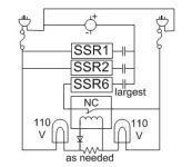
This circuit isn't really part of the above, but I mentioned it earlier, and probably nobody understood what I was getting at. We in the US tend to have rather wimpy wall power, especially if you are connecting to someone else's power where you can't be sure of the breaker capacity. This is a circuit so you can have 2 cords (with GFCI plugs) coming from your charger for double the power. The danger is that you could connect to outlets on different legs (220). If that happened with this circuit, the relay would open and the bulbs would glow. The resistor would be needed if the bulbs flow more current than the relay uses, and the diode wouldn't be needed with an AC relay. With a processor, you would disconnect the first 5 SSRs then connect SSR6 for 1/2 cycle every couple seconds. If current is present with SSR6 active, that cord is connected, but it could still be to the wrong leg and the relay just hasn't had time to open, so you would want the processor to wait a few hundred mS before connecting SSR6 and the other SSRs at the same time.


