Potting Batteries, Thoughts and Experiments

OK Wow. So we managed to do the tests just over a week ago, with both a high speed (240fps) camera and an IR camera recording the experiment. We were initially trying to cause a cell venting with with the bare unpotted packs but it proved trickier than expected to have a "short circuit" that would drain enough current to cause the cells to go, but not so much current as to vaporize the connecting tabs. However, with the potted units the tabs were in good thermal contact with the resin and that seemed to allow them to handle more amperage without melting apart. In the end, a long spool of copper wire served as the perfect load for this, giving us an initial ~25C discharge rate on the cells.

Have a look at the results:
https://www.youtube.com/watch?v=oBlac5gWLfI
[youtube]oBlac5gWLfI[/youtube]

It took almost 2 minutes of short current flowing during which the batteries drained over half of their energy, before finally something went open circuit. At that point in the test you can see that cell#4 is clearly hotter than the others, but it's not until the current has dropped to 0 amps that things really get exciting, and then one by one nearby cells that were just hot now start to go thermal too. We sped up the IR video feed to 5x rate but whole process took about 20 minutes before the pack finally started cooling again.

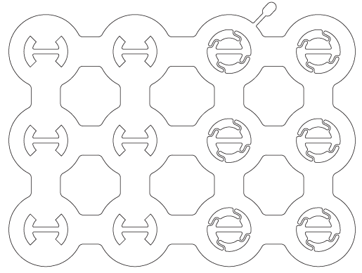
To the credit of the cells and the enclosure there were no flames or fireballs, but still quite a lot of unpleasant smoke and charring. Here's what the pack looked like after the fact. The blue/red/yellow colours on the right was us just doing a quick experiment with drops of dye on the fibreglass cloth before potting.
Pack Post Short Test.jpg
 
it appears that the spot weld on the terminal of cell #4 was where the heat was concentrated and what led to forcing #4 into thermal runaway.

was there anything obvious about the type and number of good weld contacts on those spot welds that seemed notable? did #4 go open circuit because it popped the pressure relief plug?

way cool,love this stuff where people can see what temperature it is when it goes into thermal runaway so they know how to stop the thermal runaway by quenching it in water as soon as possible in an emergency.
 
Ypedal said:
Orders of magnitude better than this mess !!

Thanks YPedal, I guess it's always nice to have some kind of reassurances that things could wind up way worse!

dnmun said:
it appears that the spot weld on the terminal of cell #4 was where the heat was concentrated and what led to forcing #4 into thermal runaway.
was there anything obvious about the type and number of good weld contacts on those spot welds that seemed notable? did #4 go open circuit because it popped the pressure relief plug?

So I did my best to cut away and scape off the charred fiberglass under the bottom of the pack to see if anything looked different around cell #4. Have a look:
Chared LiGo Bottom.jpg
First, I was surprised by just how in tact most of the enclosure still was, even though the resin had been burned/charred right through in some places, the glass fibers maintained a full wrapping and it took a lot of work to cut away a section like this. Secondly, there didn't seem to be anything anomalous with the tab or tab weld around cell #4 (4th from the right in this picture, since it's upside down relative to the video). And finally, I was surprised at just how clean and in tact the cells and tabs were. I suppose it's just because there was no oxygen in the environment while they were heating and venting so that the metal wouldn't corrode.

way cool,love this stuff where people can see what temperature it is when it goes into thermal runaway so they know how to stop the thermal runaway by quenching it in water as soon as possible in an emergency.

I'd still love to know if the reason that subsequent cells went into runaway like 10+ minutes after the current stopped flowing is because of adjacent heat transfer, or if instead the adjacent cell cans ended up shorting together as the heatshrink separators would have surely melted away, and that's why they kept going off. I'm tempted to try this test again but using a mica separator between each of the cells to ensure that there's not possible can to can shorting to see if it's the same domino effect.

If it IS the same and so not a result of adjacent cells shorting, then I'd be very curious to try the same type of experiment with an Allcell pack that has the Phase Change Material to see if that's sufficient energy absorption to stop this kind of thermal propagation.
 
i could not see any defects in the welds on the 4th over, but the 5th shows a big divot that is missing from the serial strap where one of the spot welds would have been.

i think your video is more experimentation than allcell has done. it appears that the heat is transferred through the metal tabs and not through the case and i was thinking that maybe the spot welds would show why the resistance heating was focused there on the ends of the cans in the FLIR. it could be the connection between the current collector and the can inside too.

since the heat is transferred through the metal tabs and into the case through the current collectors then that section at the top of the separator where the current collector is located may be heating the separator enuff. you should be able to find some data on the melting point or fatigue point of the polyolefin the separator is made from. then use a grinder and cut off the tops and look at the current collector and separator. if not melted in place you may be able to extract it and unroll the jellyroll. and look at the contacts between the current collector and cap under the popoff to see if any are distinctive.

i just do not see how the phase change material will have much effect on the heat transfer through the metal parts. it does not appear to go through the cases but the fact that FLIR does not show case heating may be indicative of the fact that the heat is transferred away from hot spots inside more effectively when there is large surface areas to radiate from.

i would hope most can come away from this also recognizing that it is not cell voltage that causes it to go into thermal runaway but the heating of the cell. so many people think just charging it up will make it explode. by the time your cells had entered thermal runaway they were already down below 2V i am assuming because of sag in voltage of the short and the SOC they had reached already during the discharge. that would be another data point to record too.

very well done experiment imo. the fact it takes longer to force the others into thermal runaway should give users incentive to be squirting their water bottle into the battery case right away instead of thinking there is nothing they can do to stop it when it occurs. or getting out the dikes and cutting the pack apart at the tabs while it is smoking.

i wonder also if there would be a difference in behavior if the serial connections were soldered using the little short pieces of copper tab with 4mm^2 cross section soldered onto the edge of the can bottom. instead of the spot welds in the center of the bottom.

i think the manufacturers may recommend avoiding the middle with the spot welds because of the hollow core used now so the venting does not eject the jelly roll during thermal runaway. the spot welds may seal the perimeter of the hollow core opening to the case and block it's effectiveness in releasing the gas pressure up that central core to the vent popoff.
 
are you going to cast any like this, but with a silicone shell?
 
dnmun said:
i think your video is more experimentation than allcell has done.

allcell has quiet a few papers out there showing it does prevent thermal runaway (but control pack is closely packed). allcell works but is heavy. would be interesting to compare allcell vs open pack with same cell to cell spacing
 
These experiments and posted pics/data are one of the reasons this site is awesome, and also why I am so appreciative of Justins efforts. These particular kind of experiments are quite useful because there has been a dramatic new interest in spot-welding custom battery packs, and the general trend for the home pack-builder is to simply use un-fused nickel strips.

I mention this because I have been reading about respected battery suppliers going to individually fused cells, which would stop a runaway thermal event. However, melt-downs will occasionally [and sadly] continue in the DIY garage spot-weld pack world.

The first image is a drawing (for a laser-cutter) of a metal bus-plate that provides four "S" shaped fuses per cathode/positive "button" (the six cells on the right-side half), and the pic below is the single fuse-wire to the cathode of an individual cell in a Tesla automobile pack.

JT9M6Jd.png


file.php
 
spinningmagnets said:
I mention this because I have been reading about respected battery suppliers going to individually fused cells, which would stop a runaway thermal event. However, melt-downs will occasionally [and sadly] continue in the DIY garage spot-weld pack world.

The first image is a drawing (for a laser-cutter) of a metal bus-plate that provides four "S" shaped fuses per cathode/positive "button" (the six cells on the right-side half), and the pic below is the single fuse-wire to the cathode of an individual cell in a Tesla automobile pack.

Yeah, but to the topic of this particular thread, the presence of potting material around any thin metal tabbing material seems to dramatically increase the current handling capability before the fuse section would melt apart. So if one was to take a pack with laser cut fused tabs like this designed to open circuit with excessive current, and then pot the battery as I'd done, then there's a good chance the fuse behavior would be heavily altered and wouldn't offer the same protection that it does in still air.

As a result of these experiments, I'm heavily leaning towards having a fixed SMT fuse on the BMS PCB, so that in the event that a BMS fails in a way that the ouput fets are fried (and hence always ON), then if there was a short on the terminals there would at least be a fuse to prevent the scenario that I video taped. We'd just have to be exceedingly careful that in the BMS design proper there is no chance of the fuse ever blowing during normal use, since it's not replaceable. Previously I'd been counting on the tab material providing the fail safe in this scenario since that's what happens in open air. Not so much when it's potted.
 
Am I right in thinking that the greater the initial temperature of a cell (due ambient or operating heat), the less time at short circuit is required to initiate the runaway process? If so, maximum pack operating temp. may be what determines the fusing point.
 
justin_le said:
I'd still love to know if the reason that subsequent cells went into runaway like 10+ minutes after the current stopped flowing is because of adjacent heat transfer, or if instead the adjacent cell cans ended up shorting together as the heatshrink separators would have surely melted away, and that's why they kept going off. I'm tempted to try this test again but using a mica separator between each of the cells to ensure that there's not possible can to can shorting to see if it's the same domino effect.
.

My money from my experience is heat transfer and not shorting..
I recommend you do the experiment in the dark to see the orange glow.

I had my first battery fire a few weeks ago, interestingly I am wondering now if it was on the exact same day as your experiment I might try and work that out later.

But I had a 18650 pack that were in cell holders and I wanted to see if it would fit in this bag I bought from aliexpress that I had in mind for placing the pack in, I knew it was going to be a tight fit and I hadn't done any pre-measuring.

So I dropped the half built pack into this bag and after about 30secs heard a hiss... then smoke..
I ran to the outside door and emptied the bag on the concrete and out came the pack with one 18650 cell falling out alone by its self.

It was a the very end corner cell and it had melted right out of its plastic cell holder..
On the concrete in the darkness I then watched in kind of terror as it started to slightly change shape going a bit fatter (but perfectly even, appeared to be expanding casing metal due to heat) then glow hot orange just like hot lava at night, it was a wild scene as I kind of looked at this little cell and thought right now that thing looks like the most pissed off thing on the planet..

The orange after 15seconds? dimmed away and that was the end of it, I just kicked the cell after a few minutes into a puddle where it was still hot enough to sizzle.

Looking at some chard bits I found a metal zipper puller tab that was half melted in half, I believe this had been sitting at the bottom of the bag and helped create the short.

I learned from this just how amazingly hot these cells get and I reckon seeing a bunch of them close together with only 1 cell being shorted at night time would make a great video.


Add/Edit After looking at this cell more closely I noticed how incredibly deformed particular 18650 cell is..
https://goo.gl/photos/GdH1Eb1Q7CmWWzgGA
I now believe this was a cell I received that appeared to have been run over by a fork lift or something of that nature..
I think I added it to my half built experimental pack because it was the last one sitting around and just wanted to finish the row.. So thats my safety tip to everyone, never add extremely deformed 18650 cells to your pack.

My theory as to why I received 18650 cells that had been run over by a folk lift when delivered via mail was because I ordered Rosin flux among other things in the same order as well as electrical switches etc, because rosin flux comes from tree sap ( https://en.wikipedia.org/wiki/Flux_(metallurgy)#Rosin_fluxes ) I believe it may have shown up as organic material on boarder customs x-ray machines. Because every part of my package was ripped apart, even the little switches individually bagged were opened in a fashion that resembled an attack of desperate monkeys. I believe the postal folks must of believed there were drugs inside..
So I guess thats another tip, never order rosin flux and 18650 cells together as you greatly increase your chance of your package being intercepted by dodgey postal workers.
I ordered a lot of 18650 cells from the same online seller over time and I don't think its a coincidence that the only package order to go wrong was the one that I ordered rosin flux with.. Also the rosin flux container labeling was purely Chinese writing so it would be hard to know what it was.
 
TheBeastie said:
I recommend you do the experiment in the dark to see the orange glow.
You don't think the thermal camera can see the heat? ;)
 
amberwolf said:
TheBeastie said:
I recommend you do the experiment in the dark to see the orange glow.
You don't think the thermal camera can see the heat? ;)
It just looks way more cool with the naked eye. Also in grintechs youtube description it says "Unfortunately the IR camera sensor maxes out at 150oC, so we're not quite sure just how hot things got in the process."
But yeah I see your point, somewhat..
 
Very interesting discussion and video. Sure beats a LiPo fire...

Since the purchase price of batteries is so dependent the shipping cost, I would think the purchase cost of 100W packs could be a fraction of a larger pack, since those don't need special handling when shipping or flying.

When flying, technically you can only bring 2 100w packs, and you can't fly with them internationally (since January 1, 2015, he regulations, published by the International Air Transport Association (IATA), prohibit transport of lithium metal batteries (shipped without equipment) on passenger aircraft),

You can ship two packs in a package, Thus, two 100w packs could be shipped with simple assembly instructions (wiring in parallel) to make a 200w watt pack upon delivery.
 
chas58 said:
Very interesting discussion and video. Sure beats a LiPo fire...

Since the purchase price of batteries is so dependent the shipping cost, I would think the purchase cost of 100W packs could be a fraction of a larger pack, since those don't need special handling when shipping or flying.

When flying, technically you can only bring 2 100w packs, and you can't fly with them internationally (since January 1, 2015, he regulations, published by the International Air Transport Association (IATA), prohibit transport of lithium metal batteries (shipped without equipment) on passenger aircraft),

You can ship two packs in a package, Thus, two 100w packs could be shipped with simple assembly instructions (wiring in parallel) to make a 200w watt pack upon delivery.

Incorrect information. The quantity limit only applies to battery packs/bricks which exceed 101Wh (NOT WATTS, btw) Since I got into MR (multi-rotor) or drone AC this past year I’ve learned quite a bit about flying domestic with RC Lipo. There's no limit on the number of Lithium packs you can carry on as long as they're under 100Wh. For example, 4S 5Ah brick is 74Wh.

FAA regs about Lithium ion (rechargeable) batteries, Carry on only, but the quantity limits are actually very gracious and I know several folks including myself who regularly fly commercial domestic with numerous RC Lipo bricks as long as the labelled capacity of individual bricks/packs doesn't exceed 100Wh.

READ HERE:

https://www.faa.gov/about/initiatives/hazmat_safety/more_info/?hazmat=7

Main points:

Size limits: Lithium metal (non-rechargeable) batteries are limited to 2 grams of lithium per battery. Lithium ion (rechargeable) batteries are limited to a rating of 100 watt hours (Wh) per battery. These limits allow for nearly all types of lithium batteries used by the average person in their electronic devices. Passengers may also carry up to two spare larger lithium ion batteries (101-160 watt hours). This size covers the larger after-market extended-life laptop computer batteries and some larger batteries used in professional audio/visual equipment.

Quantity limits: None for most batteries. There is a limit of two spare batteries per person for the larger lithium ion batteries described above (101-160 watt hours per battery).
ed
Batteries must be protected from damage.

Battery terminals (usually the ends) must be protected from short circuit (i.e., the terminals must not come in contact with other metal). Methods include: leaving the batteries in their retail packaging, covering battery terminals with tape, using a battery case, using a battery sleeve in a camera bag, or putting them snugly in a plastic bag or protective pouch.

My personal experience is that as long as the leads are insulated and bricks clearly labeled with Wh information and they're also in decent shape (not puffy) TSA rarely even blinks an eye passing through security screenings at numerous airports I've flown with my Phantom and 6qty 3S 2.2Ah/24Wh RC Lipo bricks/packs.
 
I have been building fused packs for testing for a few months now, using the resistor leg method, and all that is needed is a little air gap to keep the fuse from heat sinking. Why not adhere a clear plastic cap over the fused terminals before potting, it would double as an inspection window.

I have also been wondering if snaking a cooling line into the gaps prior to potting would bring us measurable cooling when paired with a small radiator. We could use a thermostat set at 130 f (55 c) to control the fan/pump.
 
Great info!! So awesome to have someone out there willing to go above and beyond for real-world KPIs - and even more-so having access to your results!!

Were all these test units made with brand-spanking-new cells? Have you tested any separate cell brands or assuming all 18650s would be similar?
 
Interesting experiments Justin. I bet that garage still smells bad now? :D

Several years ago I potted a small pack of A123 M1 cells so they could be inserted into the frame of a trike - I've used the pack sporadically ever since with no problems (just cells potted with BMS pigtails and power cables coming out one end).
However at the beginning of this year whilst moving the business I sent all our old packs/cells in for recycling - they refused to take the potted pack unless I stripped it, which was very difficult to do and ended with me rupturing a cell (they were clever to dodge that bullet!). I could see this being a problem - it often worries me what our customers end up doing with their packs when they die, and this could make the problem even worse.
I wonder how much of a problem this poses for potted electronics also? I've no idea how they "recycle" PCB's - anyone got a clue about this?

Steve
 
Justin: Are these batteries for sale?

I thought this would be them, but it is a heat-shrink wrapped battery instead (similar dimensions, but not the robustness that these ones offered):
http://www.ebikes.ca/shop/experimental/b362-5lim-r.html
 
eTrike said:
Thanks for sharing your results. I especially like the traveling mindset of your design.

I think you came closer to Bosch if you include the weight of the spacers in their design (and maybe wires?). Are the fiber packs lighter than pure epoxy as well?

I've been pondering "eco" potting using hydrogenated coconut oil. My thinking is the melting point should be high enough to prevent phase change while still being a decent heatsink, akin to Allcell. It could also be removed without much difficulty if needed.

I've not heard of some of the options above, but I like the "just the outside" ideas. More air, less weight? Maybe aerogel? :lol:

Hydrogenated coconut will melt only about 30 degrees higher than virgin oil which is about 73f

I wish there was another higher melting point oil but even coconut oil is said to spoil on wiki after only six months. I guess I don't mind eating it spoiled but if my battery started case started to smell and come apart I'd notice.

in a medium hard, clear!, polyurethane rubber (70duro skate wheel scale), I want to pot four groups of 6cells, 1x6, and I should be able to glue them to the bottom of the skateboard with the same Polyurethane..as they all seem to stick great with themselves..as does silicone but I don't think silicone can be gotten as hard.


Someone above said the movement of connections is a source of failure and making a rigid encasement solves that. Can't a good flexible connection be made with just flexible wires and solder? I read not ideal but doable. Could a spot welder be used on wires? (It doesn't seem practical but what's the best conductive paste/gel/liquid out here in almost 2016)

This pic is a fail moment as I've now decided that despite argument out there that compression is a good thing, sealing these lipo cells from any expansion scares me and I'm going to cut the cells back out. Have 4 of these. Good idea?

maybe later in the thread it comes up but did Justin end up finding that first coating the batteries as well as electronics in a soft rubber first was good for expansion? Don't these cells degass occasionally and also expand a little?
 
Alex W said:
Justin: Are these batteries for sale?

I thought this would be them, but it is a heat-shrink wrapped battery instead (similar dimensions, but not the robustness that these ones offered):
http://www.ebikes.ca/shop/experimental/b362-5lim-r.html

Hey Alex, yeah in the end we decided for now just to list the heatshrunk packs and not the fiberglass potted units, since we've still got a fair bit more testing and R&D to do before this is something I'd call release worthy, lots of unknowns to sort out vs. conventional battery assembly but lots of promising characteristics too. It is an active ongoing development project for us and once I have more interesting test results and observations to share I'll post those details here for sure.
 
justin_le said:
The big downside of potting is of course that should you have a failure it is difficult if not impossible to repair, but hopefully those issues needing repair would be way less frequent. I could see being really nervous about having single 500-1000 wh battery be potted and unserviceable, but if this was instead 5-10 individually potted 100Wh packs, then it's no big deal if one module falls out, you still have the other 4-9 batteries to keep you going.

I am assuming the resin is fairly rigid, and I believe this is leading to the failures of the first test. The advantage of using a plastic case (like Bosch) is that the case is somewhat disposable in favour of protecting the cell. Like in a car, it is the crumple zone for an impact test. Following the rigidity assumption, the potted battery has no give, no area to take the impact. Accordingly, in the absence of kevlar arguably it is transferred to the battery/ cells. A fairer comparison would have been to cut down a Bosch case, suspend the same number of cells within it and drop that. I suspect the case will be destroyed but the cells will survive.

Your aim focused on skateboard style packs - I see no reason to stop there. Getting these premade series slabs of 18650s could easily be used in a bike by layering and connecting P, simplifying 18650 batteries to a RC lipo like build. I think there is a large market for this particularly for 'battery box' bike frame owners as a simple BMS with plug in slabs would reduce battery building to lego. This concept is exactly what I am intending to use (not potted) for the next ebike. (the use of one of these frames reduces the relevance of the drop test. The frame itself protects the cells, a vibration or heat, as discussed below, becomes more relevant).

It would also be interesting to see what the battery temps are like in operation, particularly with regard to the slab situation. DIY batteries now typically use either hot glued direct cell contact or black square structures to modularise the battery. The former relies on the theory that the batteries will conduct the heat faster than air, the later structure allows for air between the cells to relieve heat within the pack. Some testing here would also be very valuable - so far I have only found people assuming or hypothesising that these theories hold true.

In this thread, others have discussed the option of potting with silicon or a silicon sleeve. On impact, theoretically the silicon will be softer and will 'sqidge' instead of cracking to reveal and expose the battery to direct impact. This could be further improved by using a case capable of supporting the silicon. It would be very interesting to see how your kevlar outer skin or alternatively, an aluminium shell would perform (or both).

If you used a cell struture approach with the plastic 'holder' to modularise the cells, tab weld then dual sleeve with silicon (have a hole at one end. Sleeve from one side, lubricate, then drag a sleeve over it from the other side) the pack could be more shockproof, accessible for servicing and waterproof. This achieves the goals you have already set and overcomes the remaining problem of accessibility. Encase with aluminium/ Kelvar and drop test. :p

Alternatively, if you stick with a rigid resin design, why not create an interlocking split design, like a case with a top? use silicon as a sealant to hold the case shut whilst maintaining the ability to cut the seal and access the cells at a later date?

Food for thought, mostly assumptions and theory rather than actual knowledge. Rereading this sounds so critical, but really I think you are onto something awesome here Justin, I want it to work! 8)
 
Back
Top