icecube57
10 MW
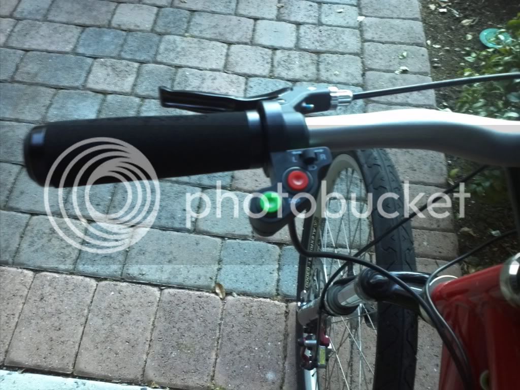
Ive had people lose controllers from trying to power the ignition line. I didnt tell them to do this or even hint at it.... it look like that was the correct place to plug it in and they paid dearly for it. I even tried doing something similar in my early days of ebiking so i dont blame them. Trying to run 72v but not upgrade the input resistors so I ran 36v to the ignition line... it made it out the driveway before the controller died.

") simple controller on/off FTMFW
simple controller on/off FTMFW