PSI / YESA 40138 LiFePO4 Cell Test Data

AndyH

10 kW
Joined
Jun 9, 2008
Messages
547
Location
San Antonio, TX, USA
Here's a quick link to my current round of cell testing. I'm using a CBAII, the partner 10X amplifier, a LaMantia analyzer, and a dozen or so VoltPhreak chargers. The cells are C-LiFePO4 40138 from Yesa http://www.yesa.com.cn/product_cells.asp?lb=2&id=2

I've started with fresh cells and documented capacity gain due to cell break-in and discharge info for 5A thru 100A (10C) steady rate discharge.

http://funwithlithium.blogspot.com/

I'll edit this post later to move the data over to our 'brain trust'. :wink:

Andy
 
Cycles one thru 14 show capacity gain as cell breaks-in. Discharged thru a standard CBAII. Charged with Voltphreak 2A chargers - from 2A thru 10A initial charge rates.

break_in.JPG


1C thru 4C (10A thru 40A) discharge in 5A steps. Standard CBAII and partner 10X amplifier. Cell connected to amplifier with two strands of 10AWG wire and crimp-on ring terminals.

10-40A.jpg


3.5C thru 5.5C (35A thru 55A) in 5A steps

35-55A.jpg


5.5C thru 7C (55A thru 70A) in (you guessed it) 5A steps

55-70A.jpg


10C (100A) pulses. The 10X amplifier lets you cycle power during a test. I started 15 seconds on, 15 off and moved to 1:30 on.

100A.jpg
 
For us dummies, what kind of cell, from where was this?
 
AndyH said:
10C (100A) pulses. The 10X amplifier lets you cycle power during a test. I started 15 seconds on, 15 off and moved to 1:30 on.

100A.jpg


In the blog, you mention that "CBA reported a cell capacity of 16.4Ah."

I'm not sure how the CBA(or what it is, really) was connected to your testing regime, but does that cell capacity measurement only include the times when the load was powered on? If it does the analysis by direct measurement of the above picture, than I guess it's understandable how it could be so high.

If not... I need some super-caps!(Use a higher running voltage, proper PWM and reserve capacitor to maintain the proper voltage and to deliver the same amount of average power over time and extend usable capacity! What a deal!) :lol:

Do you know if "pulsing" usually has a negative effective on the cycle-life of a battery relative to continuous discharge of... "comparable" magnitude(equivalent average power over time)?
 
swbluto said:
I'm not sure how the CBA(or what it is, really) was connected to your testing regime, but does that cell capacity measurement only include the times when the load was powered on? If it does the analysis by direct measurement of the above picture, than I guess it's understandable how it could be so high.

If not... I need some super-caps!(Use a higher running voltage, proper PWM and reserve capacitor to maintain the proper voltage and to deliver the same amount of average power over time and extend usable capacity! What a deal!) :lol:

Do you know if "pulsing" usually has a negative effective on the cycle-life of a battery relative to continuous discharge of... "comparable" magnitude(equivalent average power over time)?

The test was certainly in the 'abuse' category. The cell is only rated 10C (100A) discharge for about 15 seconds. I started with 15 seconds on/15 off and went up to about 90 seconds on. The last couple of short pulses were like 'wringing' the last few electrons from the cell as I shut the load off just before the cell hit 2.1V.

At at continuous 100A load the same cell only gave up about 8Ah. I was surprised to see the 16Ah number, but all the other discharge tests have been continuous. What should an e-bike 'urban drive cycle' look like? :)

The test load is a West Mountain Radio CBAII with their 500W '10X' amplifier. http://www.westmountainradio.com/CBA.htm http://www.westmountainradio.com/CBAAmplifier.htm The cell is connected to the amplifier with two strands of 10AWG wire about 9 inches long. Ther's still some load when the amplifier is turned off - the smaller CBA is handling 10% of the test load. The 'division of labor' as I understand it for a 100A test should be 90A for the amp and 10A for the basic CBA. So the 100A discharge should be 100A with the amp 'on' and 10A with the amp 'off'. I'll verify this in the next test. The CBA/Amp combination is reporting low by about .2V at heavier loads. There's an option for 'remote sensing' the cell voltage during a test. I'll look at this as well.
 
Hi AndyH,

I see you are well equiped hardware-wise to test cells, but I think there is some problem with your graph, particularly the last one that gets over 16Ah from pulsing your cell.

I think your "AmpHrs" scale (X axis) is actually "time", don't you think? Your CBA software should accumulate instantaneous Amp*Volt readings (Watts) over time, and since usualy the current is constant during such a test, the graph becomes voltage(Y) vs discharge time(X). Your CBA software will then calculate the area under the curve to figure out how many Amps-hours have been used, and thus also how many watt-hours also have been used.

Mind you I've never used a CBA, so I don't know how the software works, or how those graphs were made. But something does seem strange...
 
dogman said:
For us dummies, what kind of cell, from where was this?

miro13car said:
Andy
so what cells are we all talking about?
Brand , from where
MC

I was wondering, as well. Google seems to bring up scores from LiFeBATT for the 40138 form factor. But, if the PSI/LifeBatt connection is to believed and that YESA is just a reseller, then Google would seem to suggest the PSI/LiFeBatt cell.
 
miro13car said:
on the side of charts it says:
"Li-ion" so it is not LiFePhosphate ??
MC

I'd imagine the Thread's title has precedence over the chart's title. :D (Although, usually, it'd be the other way around. You do make a good point.)

But... it's ok in this case. Lithium Iron Phosphate IS a Lithium-Ion chemistry. See http://en.wikipedia.org/wiki/Lithium_ion
 
I've edited the subject to include the source - Yesa. I didn't realize I could edit the thread topic... sorry... :oops:

Pat - I was surprised to see the Ah result for the 100A pulse test. This is the first time I'd pulsed the 10X amp. All I can figure so far is that by manually removing the load before the test stops automatically at 2.1V, it allowed the cell to recover a bit. At this point, 'dunno' is the best I can offer.

Andy
 
The cells come from Taiwan in their own compartments:

View attachment 49_2.jpg

They ship with connecting links and hardware:

View attachment 4cell.jpg

They're labeled and barcoded on the aluminum cell body and on the shrink wrap:

View attachment Cell_Seal.jpg

The 6mm terminal bolts are long enough for a pair of 1/4 inch ring terminals and 10AWG wire:

View attachment Cell_Ring_Terminals.jpg

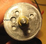
There's a vent on each end of the cell. The end caps are fairly heavy - the vent is 1.6mm deep.

vent2.jpg

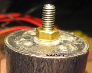
The cast aluminum ends are welded to the aluminum cell 'body' tube:

welded.jpg

It's important to keep the cell completely insulated and to eliminate rubbing that can wear thru the shrink wrap. The cell can be shorted between the terminals, and between each terminal and the cell body and end caps. For example - this cell fully charged is 3.557 volts. Voltage between the positive terminal and cell body is 1.074V; body to negative terminal is 2.482V.

I'll finish with a size comparison. The SLA cells are from my GeekSquad UPS. They're top to top with a 1/2 inch plastic spacer between them.

View attachment safecellsize.jpg
 
Cool !! that answers the question of what's under the black and red covers !! :D

Interesting that the shrink has the + and - printed on them compared to the PSI cells i got from Raymond with the white barcode stickers over and under the shrink . I wonder if yours are newer or older than the one's i have.

Be sure to keep the brass nut directly against the cell tight, i got a PDF that says having this nut loose can result in the cell leaking .. :|
 
Gaston,

The plus and minus 'artwork' is brought to you by Sharpie. Once the shrinkwrap and end labels are removed, even Ceiling Cat can't tell the difference. :lol:

Andy
 
Andy -- Great info and tests. Could you please post your current stats as how many cycles and how many AHs you're at? It would be nice to post several pics of your CBA and Amp for general info -- it's good looking equipment and seems to be performing well for you.

Has anyone been using these cells on bikes?

Thanks
 
Marketing... or 'pay no attention to the cell under the shrink wrap...' :D

I've learned a few things about these cells. First - they're capable of 10C/100A continuous (they'll run 12C intermittent).

Second - it looks like there might be only one manufacturer for 40138 cells, regardless of what color the shrink wrap is... That should make it easier for us to select a cell, and should allow us to slice/dice the tech specs and 'care/feeding' information into something usable for the group!

I'll do some more 'torture testing' of my guineapig cell...first stop - 100A/10C continuous...then 110A/11C...Wheeee!
 
Nimbuzz said:
Andy -- Great info and tests. Could you please post your current stats as how many cycles and how many AHs you're at? It would be nice to post several pics of your CBA and Amp for general info -- it's good looking equipment and seems to be performing well for you.

Has anyone been using these cells on bikes?

Thanks

Thanks! I can say that folks here on the forum are using these cells on bikes. :wink:

I ran cycle 46 on the test cell today - a 1C check-up. The call came in at 10.17Ah - down a bit from 10.26Ah peak right after break-in.

Charges have run mostly 2A, but about 1/3 of charges have been in the 6A to 10A range. I'm using VoltPhreaks 2A chargers with alligator clips and just clamping more on until I'm out of places to clip.

Once it recharges today, I'll run a couple of 100A cycles. I've run one 100A continuous and the 100A 'pulse' that's posted above with the funky 16Ah report...

Yes - I'll absolutely go over the CBA and 10X amp!

Andy
 
I've been looking for something resembling a standard 'place' to check internal resistance. Some sources say the 'best' place to check is when the cell is freshly charged, some say bleed the surface charge off first. Others say test somewhere in the middle - maybe 4 or 5Ah into a 10Ah capacity.

Whatever.

If all else fails, cheat. I scripted an automated discharge routine in to the LaMantia analyzer and decided to let the box do its thing. So we got data. :) Then I found out the box will write a log file if you ask it to...silly me to assume the log data was in there somewhere already. :oops: No pretty pictures this time around.

Yes - the box is running another discharge test...

We start with: 40138 cell fully charged, hooked up to the analyzer.
The program: Checks resistance, discharges for a set period of time at 2A. Stop if we hit 2.1V. Otherwise, repeat.

DC resistance is checked at programmed intervals with a 2A and .5A 'pulse'.

In my obscure world, D15; Ri means "discharge 15 minutes then pulse twice to check resistance".

First Ri - surface charge: 6.9 mΩ
D15: 2.3 mΩ (.5Ah - 5% gone; 95% remaining)
D15: 2.3 mΩ (.5Ah - 10% used)
D30; 2.0 mΩ (2Ah - 20%)
D60; 2.9 mΩ (4Ah - 40%)
D60; 3.6 mΩ (6Ah - 60%)
D60; 3.8 mΩ (8Ah - 80% used)
D30: 4.5 mΩ (9Ah - 90% used)
D5; 5.4 mΩ (These last 7 'over the edge' are at 5 minute and .16Ah intervals)
D5; 5.6 mΩ
D5; 5.9 mΩ
D5; 5.6 mΩ

D5; 16.0 mΩ :shock:
D5; 6.9 mΩ
D5; 8.0 mΩ

D3 to 2.1V cutoff

10.29Ah total capacity
 
The test box is a LaMantia BA402. All of the Ri samples are automatic and uniform. The operator runs thru a test lead calibration process to cancel lead and connector resistance. Each pulse is approximately one second - higher power first, then lower power.

I don't understand what you're trying to say. Do you think the pulses should be longer or shorter to be more accurate?
 
As promised, here's another view at internal resistance. This is discharge cycle 52 for this cell.

The program was modified a bit - 10 minute intervals at the 'shoulder' instead of 5 like the last program. IR sample 23 came at end of charge - the 2A pulse pulled the cell down to 1.8V.

The discharge graph with Ri sample locations marked. The numbers index to the data file to follow.

View attachment Ir_2_graph.jpg

And here's the data as reported by the analyzer:

View attachment Ir_2_data.jpg
 
I wanted to explain, that the pulses should be long enough, so the pack voltage ca settle down to its real level.

Just see some of the volt/ampere graphs with pulsed load. You'll see a fast voltage drop at first and then the drop will become slower until it drops mo more. (Like a capacitor charge curve, only opposite way ) Exponential is the math-word for it.

Am I wrong?
-Olaf
 
Back
Top