
Hello
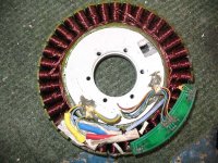
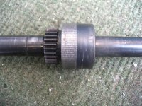
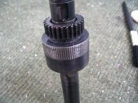
Somebody asked me if I had any photos of the Puma rotor stripped to the bone! so here they are, they were taken a few years ago, the new Puma uses a Key on the Rotor to key the rotor and the rotor bearing (seen on here with the grooves in it) to stop them both slipping, this one was stripped because the power 48V 35A had started to make the rotor slip on the bearing.
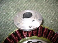
One thing that has been noticed, on the Pumas even the newer ones that the main bearing is fairly fragile, you can see on this picture the grease that appears to have spun up out of the bearing due to use and rotor speed, on high RPM pumas people running them at 60V and up you may find over time this bearing will be a problem, I havent looked in to it but it may be possible to change this bearing for something more robust? as I have seen these Seize now on 2 x pumas that were being used at high RPMS.
If you removed the phase wires and the top collet it may be possible to remove the circlip seen in the pictures and remove the bearing replacing it for another more robust unit, You can of course split the rotor from the gear however this is not for the faint hearted it took ages getting the rotor back on to this motor properly.
I had these piccies on an old hard drive thought some of you may be interested, If anybody does manage to swap out this bearing I would love to hear about it, it will almost certainly fail at some point or start to dry out, a way to check this is disconnect the battery from your controller and move the bike backwards, any significant resistance is indicative that the bearing is dry and or failing.
Good luck
Knoxie
Somebody asked me if I had any photos of the Puma rotor stripped to the bone! so here they are, they were taken a few years ago, the new Puma uses a Key on the Rotor to key the rotor and the rotor bearing (seen on here with the grooves in it) to stop them both slipping, this one was stripped because the power 48V 35A had started to make the rotor slip on the bearing.
One thing that has been noticed, on the Pumas even the newer ones that the main bearing is fairly fragile, you can see on this picture the grease that appears to have spun up out of the bearing due to use and rotor speed, on high RPM pumas people running them at 60V and up you may find over time this bearing will be a problem, I havent looked in to it but it may be possible to change this bearing for something more robust? as I have seen these Seize now on 2 x pumas that were being used at high RPMS.
If you removed the phase wires and the top collet it may be possible to remove the circlip seen in the pictures and remove the bearing replacing it for another more robust unit, You can of course split the rotor from the gear however this is not for the faint hearted it took ages getting the rotor back on to this motor properly.
I had these piccies on an old hard drive thought some of you may be interested, If anybody does manage to swap out this bearing I would love to hear about it, it will almost certainly fail at some point or start to dry out, a way to check this is disconnect the battery from your controller and move the bike backwards, any significant resistance is indicative that the bearing is dry and or failing.
Good luck
Knoxie

 Again though, I think this was caused by the jumping not the speed in this case (not least because both bikes were used offroad and not at very high speeds, and both had less than 10 hours of use on them)