You are using an out of date browser. It may not display this or other websites correctly.
You should upgrade or use an alternative browser.
You should upgrade or use an alternative browser.
Pushbutton throttle?
- Thread starter Kabbage
- Start date
I believe that will only charge the cap to 5v x 1K/(2.5K+1K) = 1.4vd8veh said:Try it like this so that the capacitor will discharge only through the 1K resistor.
I think something like this will work:
View attachment 2
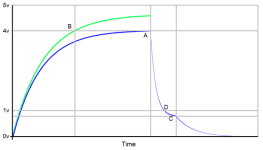
This should have a charge/discharge response like the blue curve below.
- The cap charges to point 'A' - the voltage set by the voltage divider formed by R1 and the controller pull-down (somewhere between 10K-68K depending on the controller). Ideally that voltage is about 4v.
- When the button is released, the cap discharges through D1 and R2 to about 0.7v at point 'C' (pretty quick). The lower controller throttle limit is about 1 volt so motor power should stop at 'D'.
- The cap will continue to discharge to 0v through the internal controller pull-down resistor in parallel with R1+R2. (slower)

The value of R1 is actually kind of important and depends on the controller pull-down resistor. If too large, the throttle won't reach WOT voltage (about 4v), if too small, WOT voltage will be reached before the cap is near full charge and the available time delay will be shortened as shown in the green curve above. In that case the cap voltage exceeds the max controller input voltage (WOT) at point 'B', wasting the time delay between 'B' and 'A' (the horizontal distance).
The best means to pick R1 is probably something like this:
- unplug the motor phase wires so you can mess with the controller without mishap.
- plug in the circuit and hook a DMM from the throttle sense lead to ground.
- with the button shorted, adjust R1 until the meter shows a bit above 4v (or whatever voltage gives you max motor speed - this varies from controller to controller).
- R2 can be 1K - this value controls the discharge rate and is non-critical, but will cause an unnecessarily high current draw if made too small. 1K is about 5ma - about twice the draw of a regular hall throttle - still harmlessly tiny.
- D1 can be anything handy, 1N914, 1N4148, 1N4001.
- C1 is going to be large as with the original circuit - at least 100uF and likely more. See what you like...
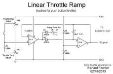
Anyhow - the aggressive initial slope of the RC charging curve is why circuits with active components and constant ramp are more attractive - not to mention the smaller cap value. This fechter smoothing circuit should be a nicer alternative - replace the throttle with a button and relocate the R1 pull-down resistor...

Kabbage
100 W
teklektik said:I think something like this will work:
Well, thanks for that idea teklektik!
I've knocked up this circuit tonight, and have tried it on the bike hooked up to a DMM like you suggested. I've used 10k for R1 (and measured 71k across the signal-ground of the controller).
It gives a range from 0-3.84V, with a nice slow ramp over about 2sec, and a quick drop. (This compares to my thumb throttle, which gave 0.84-3.71V)
Seems to work ok. I have put it on the bike, and will test it in anger tomorrow (it's pissing down with rain tonight).
I have noticed that it has a slight delay at the start - probably because it is coming up from 0V. I'll see how it works out. Sorry to keep asking, but how would you adjust this circuit to have about 0.8V on the signal with the switch open?, but still keep the slow rise and quick drop?
Okay - here's yet another version.Kabbage said:...how would you adjust this circuit to have about 0.8V on the signal with the switch open?, but still keep the slow rise and quick drop?

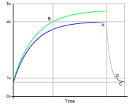
We add R3 to the earlier circuit to set the baseline ZERO throttle cap voltage which is assumed to be greater than 0.7v - the D1 forward voltage (middle image above). D1 makes this more than a simple resistor divider, but the effect is similar with R2 and R3 as the primary contributors. When the button is pushed, a slightly different divider is in play (right image above), raising the cap voltage to the WOT setting. When the button is released, C1 discharges quickly through D1+R2 and stops discharge at the ZERO throttle divider voltage. This should give curves something like this:

Because R1 does not play a role for quiescent ZERO throttle, use that case to adjust R3 first. Setup should probably go like this:
Choose a value for R3 such that SIGNAL is about 0.1v below the voltage at which the motor does not run or creep (~0.8v):
- put the bike on a stand if possible
- unplug the motor phase wires so you can mess with the controller without mishap..
- plug in the circuit and hook a DMM from the throttle sense lead to ground.
- adjust R3 until the meter shows the target value.
- test with phase wires plugged in to verify no motor motion.
Choose a value for R1 such that SIGNAL is 0.1v above the voltage that gives max no load motor speed on the stand (~4.0v):
- unplug the motor phase wires.
- with the button shorted, adjust R1 until the meter shows the target value
- test with phase wires plugged in to verify motor achieves max no-load speed
For the other values:
- R2 can be 1K - this value controls the discharge rate and is non-critical, but will cause an unnecessarily high current draw if made too small. 1K is about 5ma - about twice the draw of a regular hall throttle - still harmlessly tiny.
- D1 can be anything handy, 1N914, 1N4148, 1N4001.
- C1 is going to be large as with the original circuit - at least 100uF and likely more. See what you like...
Apologies for not trying this first, but (famous last words) it should work....
Kabbage
100 W
teklektik said:Okay - here's yet another version.Try the circuit on the left below:
Wow. Ok. I figured it started to get into a complicated sort of mess with all the resistor ratios...
I rode your first 'diode' version in to work today, and it worked pretty well actually, the small delay at the start was noticable, but didn't really impact on the operation - the power on was nice and smooth. And it didn't have the 'run-on' that I experienced with the first circuit that drained the cap more slowly. This one is a million times better in that regard.
In practice I'm not sure it'll be entirely necessary to go to the resister-wangling described here. I'll give it a go though, just to complete the experiment.
teklektik said:Apologies for not trying this first, but (famous last words) it should work....
You are apologising? Cripes - it is me that should be apologising to you, for persisting with my darned queries. You have been wonderfully helpful - a true example of the collaborative nature of E/S. You have contributed more than I could have reasonably asked for already, and for that I thank you.
That would be intersting if you get a chance. The ebikes.ca controllers look pretty slick and I'm sure getting some values that work with them would see some use.Kabbage said:In practice I'm not sure it'll be entirely necessary to go to the resister-wangling described here. I'll give it a go though, just to complete the experiment.
Unfortunately, even among Xie Chang (Infineon) controllers of the same board type, the pull-down values vary (e.g. ebikes.ca, Lyen, etc) so it's not really possible to just put some fixed value down with this strategy of using the pull-down as a critical component.
Throwing some trimpots in there is easiest, but if you are just winging it from the parts box, a handy trick to trim down a value is to parallel it with a very much larger resistor. For instance a 47K in parallel with a 560K gives about 43K (which might be about right for your R3 case).
Kabbage
100 W
teklektik said:That would be intersting if you get a chance. The ebikes.ca controllers look pretty slick and I'm sure getting some values that work with them would see some use.
I've been messing around with this tonight - I've only got a range of resistors and things I've bought for this little project - got a range since they're like 35c a packet of 10....
Anyway, I've ended up with R3 at 128k (3x64k in series), which seems a bit higher than you were expecting, then R1 at 10k and R2 at 1k. Works ok. goes from 0.4V to 4.1V or so. Not perfect, but took a lot of messing around to balance things. Burnt myself a couple of times with the soldering iron trying to replace resistors!
There was some weird stuff going on when I was trialling just R3 - it would go to a set value when I turned the controller on, then after about 2 seconds, jump right up to 4.8V or so. Same whenever I changed the R3 resistor. Anyway, I think I've got there. Perhaps the time delay for WOT is a bit long now, for some reason, so may need to go for 50microFd for the cap.
The idea really is just to cut the jerkiness when you apply the throttle, more than anything....
Thanks so much for all your help teklektik.
There is a bit of a discontinuity near 0.7v. For large R3, D1 does not conduct and the pull-down is in play (around 70K in your case). As R3 is reduced, D1 will begin to conduct and R2 comes into play - very small at only 1K. I didn't make a big point of it above, but I was assuming the case with D1 conducting so the throttle voltage would be about 0.8v to 0.9v. This funny response to the R3 value would have been easier to see and adjust with a pot - hopscotching around with fixed parts probably hid the behavior - sorry 'bout that. With the 0.4v low level, it looks like you are still running on the pull-down - which should be fine.Kabbage said:Anyway, I've ended up with R3 at 128k (3x64k in series), which seems a bit higher than you were expecting, then R1 at 10k and R2 at 1k. Works ok. goes from 0.4V to 4.1V or so.
...
There was some weird stuff going on when I was trialling just R3 - it would go to a set value when I turned the controller on, then after about 2 seconds, jump right up to 4.8V or so. Same whenever I changed the R3 resistor. Anyway, I think I've got there.
I'm not sure about the funky R3 values that caused the jump to near 5v - looks like the cap was able to charge fully for some reason (check to see that D1 didn't get zapped in the experiments) - I need to think about that one.... These fully passive component solutions are always a war of compromises because of trying to balance fixed curves and behaviors without active parts to fix things up.
Anyhow - Thanks for testing this last one out and posting back. I hope you got something that does the job for you before this little experiment turned into a career...
Similar threads
- Replies
- 4
- Views
- 342
- Replies
- 5
- Views
- 3,116
- Replies
- 5
- Views
- 1,133


