RC throttle interface build tutorial........

recumpence

1 GW
Joined
Apr 19, 2008
Messages
5,304
Location
On Earth right now. That can change at any time, t
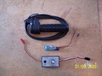
I have had numerous requests for a turn-key throttle solution for RC systems. So, to that end, I am starting this tutorial for the technically challenged who want the basics of how to build a throttle for an RC throttle interface system with off the shelf parts.

Bear in mind, I am not the first to setup a throttle like this, nor am I an electronics engineer. In fact, I am somewhat electronically challenged myself. However, I have been forced to learn some basics for the good of my hobby and the industry as a whole. I want to share a basic throttle layout here for beginners to refer to. This is obviously super simple for the very technically inclined members of our forum. But, it should help those who are not as technically savy. :D

The products I am using here are;

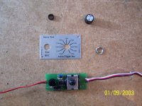
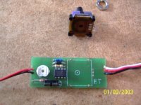
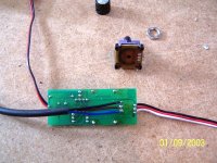
#1 Astro Flight servo tester
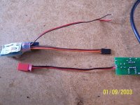
#2 Dimention Engineering VHV BEC (Very High Voltage Battery Eliminator Circuit)
#3 Magura twist grip E-throttle

You can use other brands of BEC and servo tester if you desire, especially if you want to save some money. But, these are the items readily available at my local hobby shop. So, that is why I chose them. They are also high quality and work well together.

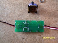
NOTE: All individual instructions are written in the caption boxes below each picture for reference.
 

Attachments

  • step1.jpg
    step1.jpg
    80.8 KB · Views: 26,878
  • step2.jpg
    step2.jpg
    78.4 KB · Views: 26,870
  • step3.jpg
    step3.jpg
    73.2 KB · Views: 26,872
  • step4.jpg
    step4.jpg
    100.5 KB · Views: 26,873
  • step5.jpg
    step5.jpg
    106 KB · Views: 26,868
  • step6.jpg
    step6.jpg
    106.3 KB · Views: 26,872
  • layout.jpg
    129.2 KB · Views: 9,794
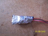
Next, once all wiring is finished, I normally wrap the BEC in tape, then foil, then tape again. This is to reduce/eliminate RF interfereance from the switching circuit of the BEC. That RF can bother the servo tester and create some glitches.

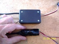
The bottom picture shows two completed throttles next to each other. The lower throttle has both boards merely taped together (using tape to insulate the two from shorting against each other). Wide heat shrink tubing can be used as well for a more finished look, as well as better durability. The top throttle has both boards mounted in a simple Radio Shack project box.

The throttle is now finished, ready to use! You merely supply 24 to 48 volts to the black and red input wires (the two bare wires hanging out the side) and plug the other wire into your RC controller, and you are ready to go!
 

Attachments

  • foilwrap.jpg
    foilwrap.jpg
    71 KB · Views: 26,838
  • finished1.jpg
    finished1.jpg
    81.2 KB · Views: 26,838
Lastly, I figured a simple way of reusing the Pot that was removed from the Servo Tester board as a throttle end point limiter.

I do not have good pictures of the wiring to do this. But, basically, you run the blue wire (from the Magura throttle) to the second Pot (the one we removed earlier). This wire should go to the center terminal on that removed Pot. Next, you run a separate wire from the terminal to the right of that center pin on the Pot to the terminal on the back of the Servo Tester board that the blue wire should have gone. This, effectively, gives you an adjustable throttle end point.

Now, this end point adjustment is NOT a current limiter. It is a throttle end point adjustment. So, when that Pot is set at 50%, your twist grip throttle will only output 50% at full throttle rotation. This limits the top speed attained and increases throttle resolution making for much smoother throttle response. This is especially helpful for high speed/power setups where you want to be able to limit speed and soften throttle response for a beginner who wants to ride it.

Adjustable throttle is shown to the right of a non-adjustable throttle.

This particular throttle was built for my 12.5kw trike. :D
 
Thanks for posting that Matt...
I'll be picking up a Magura and doing this as well.
What's your opinion of the Magura?

Seems like Magura makes throttles for pull cable throttles too.

I bought a lousy thumb pot throttle that I'm not happy with at all.
It has a weird full throttle catch which is not what you want in a throttle IMHO.
I've gone through great lengths on cars to insure that the throttle never
sticks wide open, and this company built a throttle that
does just that :shock:
Its a low tech cruise control I guess...which may be good for a low power setup.
 
I have mixed emotions about this twist grip throttle. The quality is OK, I suppose. My beef is the fact that it is all plastic. However, the plastic is thick and well molded. Also the return spring is pretty stiff. Not horribly so, but a touch stiffer than I would normally choose. Other than that, it is really pretty decent. The price is good as well.

Oh, also, I plan to make a thumb attachment for this to make a basic thumb throttle. If you picture cutting this twist grip very short so only 1/2 inch of the twist barrel is left, then add a thumb tap to the remaining twis barrel portion. Pretty simple. It could be cut to half length too for a half throttle like a half grip, twist shifter.

Matt
 
Awesome,

Thanks for the explanation. I was thinking about the half grip half twist throttle option.
That will let you grip the top part of the handle independently of the throttle.
 
Yeah thanks for posting that.

For some reason the twist grip without engine revving feels awkward to me. I think a thumb throttle would be better. Are you selling any of those custom cnc'd thumb throttles like on the pk?
 
Thanks, Matt. This is awesome. It is so much easier to understand how to construct something when I can see what needs to be done.

Cheers.
 
Cheers for Matt :)
 
recumpence said:
Hey Kim,

G'Day Mate! :D

I have to PM you. I am curious how Rhett is doing................

Matt

Yes im afraid he passed away week ago ? Matt. Helen and Rhett had previously discussed
quality of life issues in case a situation like this arose and both agreed to pull the plug if it was determined
quality of life would be comprimised, seeing Rhetts injuries were extensive AND to the frontal lobe of the
brain the decisions was made by Helen to take Rhett off like support...very sad indeed he was such a nice bloke
at least he lived a full and productive life, he flew all around the world as a pilot as well as
well as being a tragic RC addict :) Might very well be the first rider to die on a lecky bike too :-(

RIP Rhett
 
After we wire and solder it all up.....is there anything we need to do to the controller? Is there some type of calibration involved? If this sounds like a strange question allow me to clarify.

As I understand it, the FETs allow current to "pass" during the time they are on (duty cycle). If we are into low speed cruising from time to time and barely twist the throttle then the FETs will have a very short duty cycle BUT may still heat up when they are inbetween pulses. Is this correct? If so do we need to ensure a minimum duty cycle - minimum command voltage (oh, like 50% of battery V) or is this a non-issue?

Thanks!
 
If so do we need to ensure a minimum duty cycle - minimum command voltage (oh, like 50% of battery V) or is this a non-issue?

The throttle pulses aren't used to drive the output stage directly, there's a microcontroller in between in the ESC.

When you first power it up, the ESC looks for a baseline stream of pulses (1 millisecond width) which corresponds to zero throttle. If it sees these pulses, it then goes in to idle (motor stationary, ready to start).

Opening the throttle increases the pulse width proportionately, up to a max of 2 milliseconds, which is what this interface circuit does. The ESC takes care of the rest (i.e. spinning the motor). :D
 
Grinhill said:
If so do we need to ensure a minimum duty cycle - minimum command voltage (oh, like 50% of battery V) or is this a non-issue?

The throttle pulses aren't used to drive the output stage directly, there's a microcontroller in between in the ESC.

When you first power it up, the ESC looks for a baseline stream of pulses (1 millisecond width) which corresponds to zero throttle. If it sees these pulses, it then goes in to idle (motor stationary, ready to start).

Opening the throttle increases the pulse width proportionately, up to a max of 2 milliseconds, which is what this interface circuit does. The ESC takes care of the rest (i.e. spinning the motor). :D

I don't want to muck up Matt's tutorial string so I will post this as a seperate topic. Thanks for the info.

Cheers.

***************************************************************

EDIT I started a thread here: http://endless-sphere.com/forums/viewtopic.php?f=28&t=12293
 
The throttle is now finished, ready to use! You merely supply 24 to 48 volts to the black and red input wires...

Matt, sorry for a newbie question, but many of the friction-drive RC builds are using 5S and 6S (18.5V / 22.2V). What changes would I have to make to this Magura throttle adaptation, or is a generic servo-tester really the best option for the lower-powered set-ups? (I don't even know if I'm asking the right question...)
 
so if i have a hall effect throttle can i just do the same thing and replace the potentiometer in the tester with the hall or what?

im thinking i wont be able to, but i dont know how either works so im not sure...
 
spinningmagnets said:
The throttle is now finished, ready to use! You merely supply 24 to 48 volts to the black and red input wires...

Matt, sorry for a newbie question, but many of the friction-drive RC builds are using 5S and 6S (18.5V / 22.2V). What changes would I have to make to this Magura throttle adaptation, or is a generic servo-tester really the best option for the lower-powered set-ups? (I don't even know if I'm asking the right question...)

My current throttle I am building uses a very wide range input regulator. You can go as low as 6 volts input, if I remember correctly.

Matt
 
Just for info and to help anyone starting out ..
I just tackled this ESC /servo tester throttle mod using the Turnigy servo tester .
http://www.hobbycity.com/hobbyking/store/uh_viewItem.asp?idProduct=8296&Product_Name=Turnigy_Servo_Tester
Servodriver.jpg

PS.. initially i thought i had screwed up and got the wrong servo tester. ! but....
This actually proved simpler than the others, requiring only the insertion of one jumper (after removal of the pot) from the input "signal " pin ,to the centre pin of the potentiometer socket.
escthrottle.jpg

cimg8245.jpg

So when used with an ESC /BEC , you can simply connect the throttle via the "input" socket of the (modified) servo tester and away you go !
Nice simple , quick , clean throttle interface. ! :wink:
To recap..
1) remove the potentiometer.
2) insert a jumper lead from the input signal pin to the potentiometer socket centre pin location.
3) reassemble and plug in your throttle.

And for Spinningmagnets.. this is used on an 18.5 V system, Turnigy Kforce 100A ESC, with the 63-54 motor, and a Hall effect thumb throttle.
 
2) insert a jumper lead from the input signal pin to the potentiometer socket centre pin location.

Hillhater, could you please post a pic of this, perhaps add a red arrow?...

(also...thanks for the reply, Matt!)

edit: WOW! only $6, but they are now back-ordered!!...now waiting for another Hobby king email that stock is back in...

EDIT 2: Thanks for adding the pics! its great to have several RC-throttle options detailed in one thread (with prices, pics, part #'s, and links)
 
Back
Top