Re: 5KW 72V Controller 36 #4410 FET's, $108 #4110's $154

ok... here we go again :roll:

So I just read this entire thread twice.
I found it via this thread: http://endless-sphere.com/forums/viewtopic.php?f=2&t=38225

Now before I go too crazy... does anyone have any other threads to cross link so I can be fully informed?

some thoughts:

1) Those 4110's dont look genuine to me. I have handled thousands of them and although I can not point to anything specific - when I first saw a picture the print seems off - or crooked. Has anyone confirmed that these are actually genuine IRFB4110 fets manufactured in Mexico? As in confirmed by testing? Makes a difference... I would love it if this guy has genuine 4110's so we dont have to screw around. I can believe that he might actually have his grubbies on the real deal since you can now grab them in quantity 1 at Arrow for only $1.53

http://www.arrownac.com/parts/detail/42590206S7624301N3340
(I was having to purchase 12,000pcs at a time to get similar pricing just a year or two ago... so... that is CHEAP!)

2) Programming is not a non-starter. Reality is that most guys want programmability but most guys dont really even use it. Most of the time I just end up cranking everything to the limit and then adding more solder to the shunt. I would be more than willing to explore these controllers. We now have a 3spd switch that can go inline with any controller and can be adjusted for anything from 0% - 100%. The CA can handle most other basic stuff... For me - I will just set it as high as it will go and tune my throttle resolution to keep control of it.

3) What is up with the regulator - anybody sort that yet?

So I posted in that other thread..... then went back and deleted it.
The gist of my post is that I am gong to sample 10 of these. Depending on how easy the supplier is to communicate with I will get them as pimped as possible. Here are the things I would ask for.

*) Genuine IRFB4110 fets from Mexico
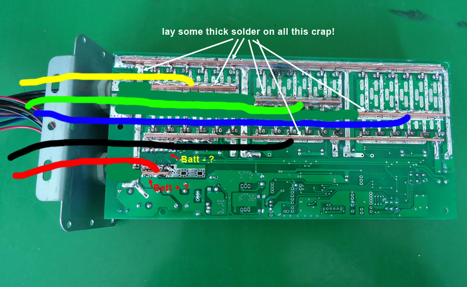
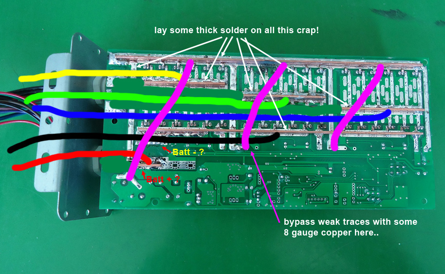
*) Heavy 10awg (or better) wires on the PCB traces
*) Try to fit larger 1000uF caps in as many places as possible
*) Add CA-DP connector. Ensure it hooks to the throttle via a diode and not ebrake.
*) Set the current limit to 100A (or as high as he is willing to set) and populate all of the shunt slots available (for increased shunt power handling)
*) Run the absolute largest Power and Phase wires that he is willing to fit in there. 10AWG at a minimum.
*) Extend the Phase and Hall leads to 1.5 meters
*) Request JST-SM (black, same style as CA and Crystalyte use) 3 pin connectors for throttle
*) Set the 3spd switch to 25%, 50%, 100%
*) Power switch? (that also switches the CA)

Ok - that will be a good start.
Please add to my list if you have suggestions

If he is even remotely respondent to that I will start trying for a real set of requirements including call outs for all the connectors and lengths, gasket material, power switches, etc. For starters I would be happy if he would do 10% of that shit and we can finish them off here.

Realistically this will probably just scare him off but I just as soon find out now then have to wait.
If he is willing to play ball I will bring in 50 of these and have my guys here finish them off to be plug and play compatible with Ebikes.ca and Crystalyte gear.

If anyone wants to get in on this action let me know. I will front the dough and shield you from any shit that hits the fan. Not sure how it will turn out - but it is not like this will be the first time I shot a wad of money into the dark vagina called China. :roll:

-methods
 
Just to be clear, are you saying that since you feel most people ask for programming, but do not actually use it in practice, that you will or will not be putting pressure on him to allow us to do programming

If you are buying quantities of them, then maybe he would be more inclined to give you programming info, you could then spread the info to us. :) your bigger buying clout may help to persuade him if you lean on him a bit
 
Methods, i look forward to seeing what will come of what you do.. i am in the market for a 36FET 4110 as of now, to drive the motenergy 4201 and MAC 2kW motors to their limits.

I don't see anyone making the 36FET controllers available these days and if we could get our hands on these and mod them to be programmable, and all the other things you mentioned.

I want to be able to set the phase to battery ratio and regen HVC appropriately for the job, so lack of programming is a deal breaker to me.
 
I have been having so much trouble finding a source in China who will produce controllers (at least somewhat close) to my requirements that at this point I would be willing to forgo having the ability to program.

Here is the deal: They are either programmable or they are not.
If they are programmable then it is only a matter of time before we gain access.
If they are not programmable then they are what they are. A lot of the chips these days are programmed at the factory. These guys are not necessarily flashing these boards... they might just have a few options when they order blanks.

I have been TOTALLY out of the loop with this stuff for over a year but the little I have seen is showing that things are moving away from flashable chips and toward chips that have a subset of real-time programmability. I have not looked - but I am sure someone has dug into the details of how Kenny's CA-Ripoff communicates with the chips.

So... I hear you guys about the programming. If I was just buying a controller for myself I would accept no substitute for exactly what I wanted... but it is totally different when you are trying to bring something in on a larger scale to try and make it available. If I can push him into populating with a different chip that is field programmable I will - but the reality is that I will be lucky if he even puts them in a box and kicks them out onto the porch for me.

Communicating with sketchy Chinese dudes is more art than science... I still have NFC how to do it. :|

-methods
 
Regarding the APM CA .. Hardly call it a rip off, a totally different and inferior product

I do have one and a compatible controller, and am more than happy to try and intercept the data streams to/from the APM and controller chip. I have posted that I am willing to do this before, but I have no idea where to start in capturing the data
Ok I suppose some sort of RS232 adapter to USB..., T- off both the Tx and Rx lines?would that work? But how to wireit up, what to wire it to? Pair of cheap EBay RS232 to USB ADAPTERS I suppose but I need details on how to do it. Wire it etc

Then what software to log the data as it passes from APM to MCU and the other way around
I imagine two adapters, and two instances of the software running, one logging the data from APM, the other logging data from the MCU

If any one can tell me how to do this, what to buy to try,I'll happily give it a shot
Was thinking two of these eBay items

Item #: 251075129117
http://item.mobileweb.ebay.co.uk/viewitem?itemId=251075129117&index=3&nav=SEARCH&nid=36988015040
 
methods said:
I have been TOTALLY out of the loop with this stuff for over a year but the little I have seen is showing that things are moving away from flashable chips and toward chips that have a subset of real-time programmability. I have not looked - but I am sure someone has dug into the details of how Kenny's CA-Ripoff communicates with the chips.
Even Fusin's latest controller does something like this, using serial I/O with it's "analyst" display. Three buttons control stuff on the display as well as which of 10 power levels (off to max) it uses for PAS. There isn't the same kind of functionality that the "APM" or whatever it's called can do, with the Crystalyte controllers, but it's a start, and I bet someone with the ability to sniff the serial data stream could decode what's being sent and received, and test out alternate sequences taht might change other parameters in the controller (I'm sure that just like other companies, Fusin would never tell us if it is even possible to do it, much less help ;)).


@NeilP:
Capturing the data on a PC is easy--just open any terminal program and set it to the right com port. ;) Then set it to save teh file. Same way you can do it on a PC capturing from the CA's data stream to log it.

Tapping off the serial data lines should be as straightforward as just hooking up the TX and RX and ground lines.

I've considered doing it with the Fusin version here, but I dont' really have enough time to do anything with it.
 
methods said:
Communicating with sketchy Chinese dudes is more art than science... I still have NFC how to do it. :|

Oh my god, tell me about it.

I hope some of the EE dudes who hack everything they can possibly get their hands on come out of the woodworks for this. They seem to be rarer birds every passing year here on this forum.

I think there will be a higher demand for 36FETs soon, given that the 54xx and Cromotor have came out.

These probably have crap components and we'll find out what's really going on with them later but they are worth a shot..
 
Yea - I could reverse engineer the comms in a weekend but I dont even want to go down that path. The trouble is that there are 32 variants of that chip floating around with 64 versions of firmware. So lets say I get it all dialed in... problem is that 2 months later when I order my next batch of controllers they are running either different firmware or they are totally different chips. Chinese dudes just swap that shit out like they think it is funny :roll: Anyone who has been watching these "infineon" type controllers since they hit the ebike scene knows just how many variants there are out there and how randomly they change.

No way someone has not already reversed that data stream between the Kenny box and controller.... It has been out a long time.

-methods
 
methods said:
No way someone has not already reversed that data stream between the Kenny box and controller.... It has been out a long time.

-methods

but not on here, that i have seen that anyone has posted about and helped out in being able to program them :(


amberwolf said:
Capturing the data on a PC is easy--just open any terminal program and set it to the right com port. ;) Then set it to save teh file. Same way you can do it on a PC capturing from the CA's data stream to log it.

Terminal yes that is it, just have to look up the commands again to point it to the com ports and log the data...been years since my amateur radio days and doing this sort of stuff


amberwolf said:
Tapping off the serial data lines should be as straightforward as just hooking up the TX and RX and ground lines.

Just to confirm.
As I see it you have two data streams...
From APM (XLYTE CA) to the MCU.......... I'll call that Stream A = APM Tx port to MCU Rx port
To APM (XLYTE CA) From the MCU..........I'll call that Stream B = APM Rx port to MCU Tx port

So I would get two of these, to enable simultaneous logging of both streams, and just use the ground and Rx lines on each one. Rx line tapping in to a tap between Rx and Tx lines of both Stream A and Stream B..

$(KGrHqFHJCUE9qiKtE!2BPhn47NqVg~~60_3.JPG
 
I wonder if this is still going becase gordo started this thread last year lol.

NeilP do you have a link to that usb-serial adapter?
 
http://www.ebay.co.uk/itm/251075129117?ru=http%3A%2F%2Fwww.ebay.co.uk%3A80%2Fsch%2Fi.html%3F_from%3DR40%26_trksid%3Dp0.m570.l1313%26_nkw%3D251075129117%26_sacat%3DSee-All-Categories%26_fvi%3D1&_rdc=1
 
These pictures are fairly recent and should be of a current gen 36 FET 4410 Greentime controller.

6941165260_4993a8d3b7_b.jpg


6941164056_3903cba519_b.jpg


7087232809_bda7d0c053_b.jpg


The board layout looks poor, the construction looks to be exceedingly poor, and the quality of the components used appears to also be poor. I'd question how reliable this controller would be at the high power levels most people would want to run.

This is a 36 FET from the same company, over a year ago. I'm assuming this style controller is no longer available.

6941161136_acfdc3a3fc_b.jpg
 
methods said:
No way someone has not already reversed that data stream between the Kenny box and controller.... It has been out a long time.

I'll bet that Justin has. I sent him one of Kenny's new controllers about a year ago. In fact it might (maybe) have given him a couple ideas that he used in his new V3 CA.
 
Looks like crappy bits and pieces to me :(

The phase wire location within the FET layout is tragically bad, right up there with the kelly controllers..
Those copper bars do not look like they are soldered on very well either..

Could relocating the phase wires to the middle of each phase section, beefing up the traces, and hooking up the battery wire(s) in a more suitable location help the current sharing?

greentime_mods.jpg


We might not be able to get a mirror polish on this turd, but it is worth going for a glossy look anyway.
 
Yep, to coin a phrase my mate uses a lot
" You can't polish a turd....but you can cover it in glitter `' :p
 
The biggest issue definitely is the fact that all the current from the 6 FET's dumps right into the PCB, and its a long path before it hits that questionably soldered copper bus. I would guess they are not going to share current very well with a path like that, especially once things start to heat up, likely unevenly. With how it's laid out, it will be very difficult to improve it much. It's just a damn poor layout for high power.

This controller is obviously made to handle a few kW with a ton of garbage FET's. Put real FET's in and the power handling does not really rise. It's just a poor design, and I don't know how robust it will be under abuse. It's possible the PCB has super thick copper, but its probably junk.
 
You mean like on the bottom of the board, where there is a horribly weak trace going from what looks like the capacitors all the way to the top?

greentime_mods2.jpg


Can't a poor current sharing design be corrected by re-routing the power using fat copper wire to the right place?

Am i barking up the right tree?

If we can work on a ghetto fix to correct this design, then you dump some time into soldering.. buy it with the trash 4410 FETs at a loewr cost then get your own genuine 4110's from octopart ( as methods mentioned ).. end result is a $250-$350 36FET controller capable of wicked power.

This seems to be worth working with, but i've never toyed with any of this before. I am hoping some of the controller gods can chip in..
 
I dunnu.... I'm thinking... if heat is what is restraining our controllers.... and it seems to be since each 4110 can handle 75a in the to-222 package
then what we need is better cooling!

Follow with me here. Get an aluminum project box slightly larger than the normal controller case. Fill it with mineral oil. Upgrade the caps on the controller since you now have more room to work with. Upgrade the traces. Perhaps do zombiess wire to fet tab upgrade. Dunk it all in the project box.

It actually seems like a super simple mod. Like only a few hours of work. I'm honestly surprised only one person here has done it. IIRC he is running an x5 with a 12 fet controller with no problems.
 
Heat is generally the limiting factor for all electronics. The issue isn't really resolved with external cooling, generally the limitation becomes the thermal path of the device itself. The heat is not generated by the copper back on a FET, but rather on the die attached to that back, and the bond wires supplying power to it. Better external cooling only really helps you run near the limits longer, but does not generally increase those limits. 75A is a rather conservative figure for a 4110 FET, but in a 36 FET controller it might be hard to even get 75A average out of each FET unless substantial care is taken.

Solder tends to have relatively high resistance as compared to a metal like copper. It's not a cure-all solution to help MOSFET's share current, but does help to some degree. What you really want, is a well optimized electrical layout right off the bat. This controller puts the upper and lower bridge quite a distance apart, and those copper bus bars essentially reduce the available space to beef up the traces to near zero. The way to go, would be to pull the bus bars on the FET rails, and run wires right to the pads. This would allow you to have sufficient distance from the PCB to get some copper wire, foil, or pipe in there to minimize the resistance between the FETs of each phase bridge. The resistance between the upper and lower bridge to the actual phase wire would be a secondary priority thats easily solved.

neptronix, thats basically what needs to be done. The biggest concern isn't the relative resistance between the + bus on the PCB and the battery, but rather that each FET gets as close to identical resistance as possible. Just make sure the current goes through the shunt, and your picture looks to have the right idea.
 
Glad i seem to be barking up the right tree.

The programmability is what is holding me back from really experimenting with these and doing the mods mentioned.

I wonder if you can change out the controller's 'brain' chip out for one that is used in the EB3 or EB2 controllers. I wonder if the pins lead to the same places.
It would be interesting to compare the board layout to a xie-chang / keywin style 36FET controller to find out. Of course i do not have one lying around by chance, lol...

I am still a laughable electronics newb and lack equipment and only have ideas. I do hope that someone more competent can tackle this. Given enough cash and thus enough boards to blow, i could eventually figure it out ( 1,000 monkeys on a typewriter technique :lol: ).

Just blew $1,100 on eBike shit within the last month so the budget doesn't allow for much monkeying for a while. But if nobody takes this cause up, i will eventually get to it.
 
Methods,
I just sent you a msg. I put a note here because I don't know if your PM box gets flooded.

Neptronix,
I have an established relationship already. Let me know exactly what you want, though programmability is a no-go at this point. Badmouthing a controller you have 0 experience with is absolutely hilarious.

John
 
John in CR said:
Neptronix,
I have an established relationship already. Let me know exactly what you want, though programmability is a no-go at this point. Badmouthing a controller you have 0 experience with is absolutely hilarious.

John

Pictures are worth a thousand words. You've complained about yours overheating already - wonder why? It's pretty obvious that the current sharing is a joke just looking at it. I'm going off what i see and everyone else sees. Are you disagreeing that the current path is suboptimal, or just talking trash for the sake of it? :)

At the price, it is worth working with, but i'd never run one of those stock..
 
neptronix said:
Pictures are worth a thousand words. You've complained about yours overheating already - wonder why?

Wrong. It's the crap Infineon boards that need a blower with my motors. Stick with talking about things with which you have direct experience.

If my Leo36 got hot, I would have certainly mentioned it here.

John
 
John in CR said:
neptronix said:
Pictures are worth a thousand words. You've complained about yours overheating already - wonder why?

Wrong. It's the crap Infineon boards that need a blower with my motors. Stick with talking about things with which you have direct experience.

If my Leo36 got hot, I would have certainly mentioned it here.

John

OK, are you running the leo at similar power levels or higher?

The 36FET infineon board looks fairly well laid out; these greentimes look more like the kelly controllers which are famous for underperforming / overheating at a lot less than their promised current. Like liveforphysics said, the FETs don't end up sharing the current evenly... that's a problem for high performance.

Do you disagree with what he said?
 
Back
Top