Replica ebike - 1881

From "Le règne de l'électricité" (The Reign of Electricity) by Gaston Bonnefont, 1895 (badly translated from the original French):
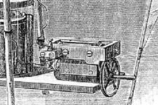
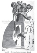
With his motor, M.G.Trouve was able to maneuver a boat on the Seine slowly. It employs preferably a dual motor, that is to say two coils, which produces more power without significant increase in weight and volume. This engine is placed on the head of the rudder, and communicates through an endless chain, with a propeller embedded in the rudder. Everything is so mobile. The battery, placed at the bottom of the canoe, consists of two trough batteries. The conducting wires pass along the man-ropes, each of which contains a switch MN designed to interrupt or start the flow. He can, through this arrangement, stop the movement at will, and besides, the propeller, which rotates with the rudder, the boat operates on the side, and thus allows stopping almost on the spot.
So I'm gonna go with just on-off switches...

Bonnefont illustrated this passage with the "usual" pic of Gustaves twin-rotor motor mounted on a stand, NOT the motor complete on the rudder...

I was a bit puzzled to read his description of the switches as "MN", but realize that the switches are labeled as N and M in *another* picture of Gustaves outboard motor (shown earlier in this thread) that Bonnefont did not show:
file.php


So just looks like Bonnefont's editors didn't catch this little slip up. :)

And, no reason to think that Gustave used these sorts of in-line switches on his trike, as these switches served double-duty as handles on the tiller-ropes for the boat...
Lock
 
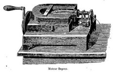
More from Bonnefont in 1895. Discussing the history of motor design...
He reaches Deprez, considered a leap in design for his arrangement of the armature between the poles:
Bonnefont_1895Deprez.jpg

Then he talks about Gustaves single rotor design... first he repeats the bit where Gustave talks about his wierd attraction to escargot (bad transalation from the French):
Trouve Motor - The complete record of the meeting, 28 June 1880 of the Academy of Sciences reproduced the following note in which M.Trouve exposes the principle of his device. "When we trace the dynamic diagram of a Siemens coil in making a complete revolution between the two magnetic poles which react on it, we see that the work is almost zero during two periods of fairly large rotation. These two periods correspond to the time during which the poles of the cylindrical coil, having reached the pole of the magnet, marched before them. During the two factions of the revolution, which are each about thirty degrees, the magnetic surfaces intended to react one on the other remain the same distance, the coil is therefore not sought to spin. This results in a significant loss of work.
"I delete these periods of indifference and increased the effectiveness of the machine thereby altering the coil: the pole faces, instead of being portions of a cylinder whose axis coincides with that of the system, are snail-shaped, so that they approach gradually turning their surfaces from that of the magnet. The action of repulsion begins, so that the break is almost avoided."

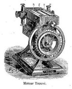
...then Bonnefont goes on:
Bonnefont_1895Trouve.jpg
Instead of using, as Mr. Deprez, a permanent magnet, M.Trouve uses an electro-magnet U, between poles aa between which is placed the modifies Siemens coil f. The current flows through the wire of the electro-magnet E, and passes through the brushes of the switch in the wire coil, the whole apparatus is crossed by the current of the battery. This current loving the soft iron electro-magnet and moving coil and magnetic poles are determined. These poles change their name to each revolution, as in the engine Deprez and is therefore produced a series of attractions which in this engine are almost constant and dominate much of the repulsions. These attractions will continue until the power interruption.
Experience shows the vast superiority of this motor versus the Deprez motor. A current, whatever its strength, can run the Trouve motor; in the Deprez motor, it is, instead, that the magnetic force powered by the current is proportionate to that of permanent magnet, so that rotation can occur with efficiency.
M.Trouve increases the number of elements, and obtains an increasing speed, always regular, nonstop, with no dead spots. This speed can be of eighteen thousand rounds a minute.
The engine is only twenty centimeters in length and weighs only four kilograms.

Holy Crapolla! Gustave was spinning his motors up to 18K RPM?! Doubt he was doing this on a regular basis, but this explains the gearing shown on all of the pics of his motors...

Beginning to think the 21st-century non-frock RC motor guyz are motor-wussies compared to Gustave...
:lol:
Lock
 
Gaston Tissandier (the balloon guy using Gustaves motors) was quite the mover and shaker... In addition to publishing the journal La Nature, in 1881 he was also President of the Société française de Navigation Aérienne (French Society of Air Navigation) watt basically meant balloonists back then. And just being blown around by prevailing winds. So there had been earlier attempts at powering balloons but folks were nervous about lighting fires for steam boilers around huge bags of hydrogen gas :mrgreen:

Hence Gastons interest in the new dynamo-electric machines and rechargeable batteries...

These French aeronauts put out a monthly journal L'Aeronaute, and in the August, 1881 issue Gaston re-printed his report to the French l'Académie des Sciences where he detailed the sort of performance he was seeing from Gustaves "mini" motor on his scale model balloon (bad translation from the original French):
ELECTRIC MOTORS AND M.G.PLANTE's SECONDARY BATTERIES AT THE DIRECTION OF BALLOONS.

The recent improvements made to dynamo-electric machines gave me the idea to use them in the direction of balloons, in conjunction with secondary cells, which, under a relatively light weight, store a large amount of energy.

A similar motor, coupled to a propeller, offers, over all others, significant benefits in terms aerostatic; it works without any firebox and removes the danger of fire around hydrogen, offering a constant weight, and doesn't give off products of combustion that offload the balloon constantly and tend to push up into the atmosphere. It starts with an ease unmatched, by the touch of a switch.

I did make a small elongated balloon, terminated by two points, 3m,50 in length and 1m,30 in diameter in the middle.

This balloon has a volume of 2200 liters. Inflated with pure hydrogen, it has a surplus upward force of 2 kg.

M.G.Trouvé built a small dynamo-electric machine, like Siemens, weighing 220 grams., and whose shaft is fitted through a transmission, a propeller with two arms, very light, of 0m,40 diameter. This small motor is attached to the bottom of the balloon, with a secondary cell weighing 1 kg.300. The propeller, in these conditions, turns 6 1/2 revolutions per second; it acts as a propellant and pushes the balloon, in a calm, at a speed of 1m per second, for more than 40 minutes. With two secondary cells mounted in tension and weigh 500 grams. each, I can adapt to the motor a propeller 0m,60 diameter, which gives the balloon a speed of about 2m per second, for ten minutes. With three elements, the speed reaches 3m. I repeated the experiments many times with the balloon mounted on a carousel installed in a room in the Conservatory of Arts and Trades that Mr.Hervé Mangon kindly put at my disposal.

After these first tests, I have measured the work produced by the little Trouvé dynamo-electric motor. I used the simplest method, by lifting weights directly to the motor. These experiments were performed with the assistance of M.E.Hospitalier. We connected the motor with a secondary element, then two elements in tension and we varied successively speeds, increasing or decreasing the value of weight lifted. The small engine, which, again, weighs 220 grams., produced under conditions of maximum work, 90 grammetres with a single element and a speed of 5 revolutions per second. With two elements in tension and a speed of 12 revolutions per second, the work reached 420 grammetres; with three elements it reached about 1 kilogrammetre.

With two elements in tension, if the speed drops to 5 or 6 turns per second, the work is more than 278 grammetres; if the speed is greater than that corresponding to the maximum level of, say, 14 revolutions per second, the work is more than 375 grammetres. These experiments show that according to theory, the electric motors coupled to a generator give up a job which corresponds to a certain speed.

Under actual conditions, the dynamo-electric can give 6 horsepower under a weight of 300 kg. approximately, with 900 kg. secondary elements. It would be easy to lift this material with you, with a total weight of 1200 kg. in an elongated balloon, inflated with 3000 cubic metres of hydrogen, similar to those conducted in the air in 1852 by Mr.Gifford, and in 1872 by Mr.Dupuy de Lome. The balloon would be 40 meters long and 13m,50 in diameter in the middle, and total upward force would be about 3500 kg.; it would weigh with all rigging, 1000 kg. to 1200 kg, it would remain so even more than 1000 kg. for passengers and ballast. In calm weather, the balloon would have a proper speed of 20 km. to 25 km. per hour, and in moving air it deviates from the line of wind and it certainly would work only for a limited time, but could be used for demonstration experiments all at crucial fact. The results would be even more favorable by using a dynamo-electric motor and secondary battery constructed in special conditions of lightness. It would thus, under the same weight, an amount of energy much greater.

I have the honor to operate before the Academy, the motors which I used in my preliminary experiments, executed in miniature.

Gaston TISSANDIER.
(From the weekly reports of meetings of the Academy of Sciences).

"...6 horsepower under a weight of 300 kg."
That sucks :) Miserable power density at about 7W per pound...

"...maximum level of, say, 14 revolutions per second..."
So, 840RPM...

Gaston doesn't say but I believe he would have been referring to prop speeds, ie output shaft RPMs after the gear reduction.

I believe he was using Gustaves single-rotor design including the gearing:
Trouve_gearing.jpg

But lots of stuff I don't know about the gearing... How accurate any of these pictures are... Whether Gustave was using the same gear ratio for Gastons model balloon as he used on the trike and boat...

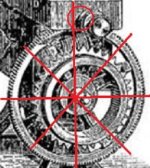
Bonnefont provides the best image of Gustaves single-rotor motor w/gears and a rough count for the large gear comes out about 148-150 teeth:
Trouve_gearingb.jpg

...but then I have no idea of the size of the small gear on the rotor shaft :?

WAG, 30 teeth? If 30 teeth, gear ratio would be about 5:1 ... That'd take Gastons 840 max RPM up to 4200RPM for the rotor...

I do know that EVen though Gustave gave up on electric trikes and mostly sold his larger motors to the yachty crowd (kinda makes more sense where heavy lead packs can be an asset aka ballast,) he did continue to work on light weight motors... Read one report where some years later he had a motor with aluminum wiring and an air prop that achieved vertical lift-off - it could lift it's own weight. Gotta know that air prop design got a lot better in the years after the Tissandier brothers got their real balloon off the ground in 1884...


tks
LocK
 
WAG, 30 teeth? If 30 teeth, gear ratio would be about 5:1 ... That'd take Gastons 840 max RPM up to 4200RPM for the rotor...

Working backwards...

Reports vary about watt sorts of max. speeds Gustave was seeing on his trike... 12kmh, 12.5kmh, 10mph... etc.

In my neighbourhood at these speeds I would be run down by small children on their pedalbikes... if the SUVs don't get me first...

20km/h fits me in with the urban commute bike crowd. So I'm OK with that.

AFAIK the Coventry Rotary wheels were shrunk a bit over the years of production. Most are described as having a 48" diameter wheel for the main driver. But two of the earliest Lever Coventries are described as having 50 inch. Soooo...
50in. diameter
157in. circumference
157 inches = 398.78 centimeters
max speed 20km/h
5015 revolutions per hour
83.588RPM

For the motor that Bonnefont shows that has a chain sprocket mounted on the large gear, the sprocket has exactly 35 teeth...

If Gustaves motor were max'ing out at 4200RPM rotor speed and outputting 840RPM through the gearing, to get to 84 RPM the chain reduction would have to be 10:1, and the final sprocket on the axle would be only... errr... 3.5 teeth :mrgreen:

So that's not gonna happen... Wonder watt the smallest tooth count might be for a sprocket wrapped by some sturdy Vaucanson chain... hmmmmm...

Thinkin' Gustave musta been spinning his trike/boat rotors at much lower RPMs than implied by some of Gastons numbers for his mini-motor.
Lock
 
In 1894 Henry de Graffigny wrote an article in "L'Industrie Vélocipédique", the trade magazine for the French bicycle industry. The title of his piece was "LES VOITURES ÉLECTRIQUES"... (Electric Cars)

He goes into how horrible the steam and gasoline vehicles are, and all the things that make EVs great. Then he provides a history of EV development to that point, starting off with Gustave in 1881, quoting an earlier account written by the Abbé Moigno which the Abbé originally published in his own scientific journal "Cosmos". The Abbé died in Paris in July 1884, so his account was probably contemporary, and being a science-minded guy, may have seen the trike himself. (as always, poor translation from the original French):
The first application of this fluid at the start of an apparatus for locomotion appears to date back to the year 1881. The electrician G.Trouvé had the idea to drive the wheels of a tricycle with two small electric motors of his invention receiving the current from a Plante storage battery. Here is a description of all data at the time by the learned abbé Moigno in an issue of his scientific journal le Cosmos (Les Mondes).

"On a tricycle with two steering wheels and one large driving wheel, quite heavy and of English construction I believe, had been placed below the axle, two small Trouvé motors as big as your fist, which transfer their movement through two Vaucanson chains, acting on two sprockets fixed to the axle of the large driving wheel.

"Behind the seat and below the axle, a wooden box, contained six secondary cells quite similar to those of Gaston Plante actuated the motors.

"On the seat, and left on the handle of the brake lever, well within the reach of the driver's hand, being a switch that he had only to touch to start or stop immediately.
"This, as briefly as possible, the portrait of electric tricycle, 8 April 1881, which, looking back, resembles in miniature car from old business travelers.

"He has traveled several times in the Rue de Valois its entire length and as quickly as a good taxi."

Add that this tricycle, of English Construction, indeed, was very heavy, weighing 55 kilograms. The total weight of the vehicle, including batteries and the person the amount was 160 kilograms, and the effective force produced by the two motors corresponding to 7 kilogram-meters.

This experiment, the earliest that has been successful, determined to combine M.G.Trouvé a removable device, similar to that of his electric boats, which easily applies to most tricycles which he prints, currently has speeds of 20 to 25 kilometers per hour.

This device consists of a motor with accessories and automatic battery of M.Trouve that allows long distances if care is taken to renew the salt exciter.

So turns out, according to the Abbé, Gustave had rigged an on-off switch to the handle of his hand brake... another little mystery solved. :)

No idea watt an "automatic battery" might refer to... and watts up with the mention of TWO chains???

Kinda amusing to hear that at one point Gustave was talking about selling ebike conversion kits. :D

BTW, if it seems strange that Henry de Graffigny was writing about electric CARS in a magazine about bikes, as much as he was promoting electric traction, at the end of his article he concluded that the best electric vehicles are electric trikes!
...et c'est pourquoi je crois au succès définitif de ce moyen de locomotion si éminemment agréable: le tricycle électrique!
tks
LocK
 
Getting a bit OT as there's no new info here, but it's just nice to read a first-hand account from someone that went for a spin with Gustave in his first boat. This account was published in "La Science populaire. Journal hebdomadaire illustré" on June 23, 1881:
ELECTRICAL NAVIGATION AT PONT-ROYAL

Several newspapers have already spoken of the amazing solution provided by M.Trouve to the problem of electric traction applied to boats. - We had the good fortune to attend, on the Tourist dock at Pont-Royal, one of the experiences of the author.

An elegant skiff for two rowers, christened La Telephone, equipped for a pair of oars, was moored alongside the pontoon. Between the bench of the helmsman and the first bench for rowing, there is a potassium dichromate battery composed of 12 couples zinc and carbon, grouped into two batteries mounted in tension, each element having approximately 4 square decimetres surface and affecting the layout devised, if we are not mistaken, by M.Grenet, that is to say, the zincs and carbons connected by a rod which simultaneously ensures the contacts and can be addressed through a crank to emerge from the tanks.

But until then, nothing that quite well known to most viewers, the nice, the ingenious, that's M.Trouve, a charming man by the way, very amiable and a remarkably intelligent air, brought under his arm, namely, the rudder of the boat. This rudder is all the mystery: Imagine the standard tiller supporting a mahogany frame that has certainly not more than 25 centimeters long by 15 wide and 5 or 6 thick. This frame encloses the electric motor on which we do not have to give lengthy details, but we were struck by its small size compared to its power and it seems to make excellent use of electricity. The rudder itself, metallic and hollow at its center, receives a single helix of 25 or 30 centimeters in diameter, which is transmitted by a gear movement of the electric motor.

The latter receives its power through the metal man-ropes covered with an insulator and connected by terminals to the batteries.

Three people, including the inventor, who sat in the skiff, the zinc and carbon were immersed as a mechanic who opens the drawer of a steam engine, and the Mariners pushed off, putting on a show following the meanderings of the shore crowded with boats, promenades and bathhouses.

And indeed, as we noted to M.Trouve, the skiff moving beautifully. On various occasions we have sought the means to place, in large vessels, the propeller behind the rudder so that it, escaping the reactions produced by the rotation of this, should retain its maximum effectiveness. It may well be that at this point of view, the issue was fully resolved, if the application becomes electro-motive, as we hope, useful for large vessels: the thruster body was placed in the rudder and moving with it when it was steered by the man-ropes, the direction of the driving force is to make a more or less acute, the keel of the boat, and its action, acting sideways on the stern, forcing the back of the boat to drift and the boat itself to turn, if desired, in its own length more easily than I could do pulling with two oars on one side and releasing the other. Many collisions could perhaps be avoided with this ease of development.

But unfortunately, the installation that we were shown has a weak side: it is the source of electricity we have described. This is nothing new that we recognize the problem, offered by the impossibility of transporting a liquid cell.

In addition, the bichromate battery, if it is very strong, is very expensive and runs out quickly and is especially suitable for short and intermittent action, as in the electric igniter. A dry battery is preferable, and we do not know enough energetic enough. Is there not a test to try with the Plante secondary battery, or better, with the Faure cells, experienced at this time on a tram car?

We submit this idea to the inventor, if we have the honor of being read by him. Moreover, this was probably not given the problem he had to solve. In terms of transforming the electricity into work, there is a remarkable achievement and a provision of a rare happiness.

We are far from imitating the trembling fish tail of which we had thought a few years ago. It is hoped that the attention of the Administration of the Navy wants to focus on the good experience we have described and which will not be, hopefully, the last.

L.D.

`Cause Gustave's such a nice guy, I'll add his pic to this thread. Most of the pics floating around the web show him in later years, but in 1881 he was only 42... so here's a younger Gustave:
gustave_trouve.jpg

tks
l0cK
 
Lock said:
...he provides a history of EV development to that point, starting off with Gustave in 1881, quoting an earlier account written by the Abbé Moigno which the Abbé originally published in his own scientific journal "Cosmos". The Abbé died in Paris in July 1884, so his account was probably contemporary, and being a science-minded guy, may have seen the trike himself.

Found it. The Abbé didn't write the account himself, but published a letter submitted for his journal. And de Graffigny didn't quote the full letter...

From Cosmos (Les Mondes): ("revue hebdomadaire des sciences et de leurs applications aux arts et a sciences") by M.L'Abbe Moingo, May-August 1881 (usual suspect translation):
- Motive power by electricity. - We publish the following letter we received a few days ago, and contains positive results far better established than those of the Faure battery.

- "I had just crossed the Palais-Royal and and came out into the Rue de Valois, when my attention was attracted by a man riding a tricycle, arriving with great force. I would have left immediately but, at the approach of the bicycle, I had heard some exclamation by the curious, saying: "Sure, it's steam or electricity that makes it tick. "At this word I looked closely at the passing vehicle and it was easy to recognize that indeed the soul of the movement was much electricity, because I immediately recognized the little motor which had been presented and demonstrated by its inventor at the soiree of M.le Vice Admiral Mouchez at the Observatoire de Paris and mentioned in Les Mondes Volume LIV, p. 212. I recognized the person who rode the tricycle as M.Trouve, the famous electrical engineer, afterwards I learned that he kept a window at l'hôtel de Hollande to follow all phases of the experiment.

I'll say a few words.

On a tricycle with two wheels and one large driven wheel, quite heavy and of English construction, I believe, had been placed below the axle, two small Trouve motors as big as your fist, which transmitted their movement through two Vaucanson chains, acting on two sprockets mounted on the axle of the large drive wheel.

Behind the seat and supported on the axle, a wooden case contained six secondary cells or electric batteries quite similar to those of M.Gaston Plante which drive the motors.

On the seat, at left on the handle of the brake lever, well within the reach of the driver's hand, was an electrical contact that he had only to touch to start or stop immediately.

That, sir, as briefly as possible, the portrait of electric tricycle, 8 April, which, seen from behind, looked like the small car of business travellers of old.

He traveled several times in the Rue de Valois its entire length and as quickly as a good hansom cab. -
Gaudet.

So, dunno who "Gaudet" was but he knew about Gustave and his motors and had a good look at the trike as Gustave rode up and down Valois. And he mentioned two chains...

So was Gustave running a double reduction? Or two separate motors, and not his twin-rotor variant? Hmmmmm!

And it was the Abbé that described Gustaves cells as Faures. Gaudet actually only said they looked "similar to" Plantes... Maybe the Abbé had other info that Gustave was using Faures on the trike at the time.

Lock
 
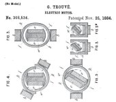
FINALLY found a copy of Gustaves patent for his motors... the US patent anyway. Seems he waited four years before applying in the US for some reason:
308534header.jpg

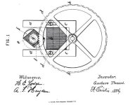
The drawings for the different rotor/stator combos I've seen before but not the "main" drawing of the motor:
308534diaga.jpg
308534diagb.jpg

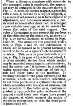
The text of the patent is predictably broad ie vague... At least his patent lawyers got him to stop going on and on about escargot:
308534detail1.jpg


No idea why he used copper for the base of the magnet and not iron or steel through-out? Or why he though the top bits aa might need adjusting? Surprised he called it a "toothed wheel" instead of a "sprocket"...
308534detail2.jpg

In summary:
View attachment 1

"...very high rates of speed..." Hehe... Bet his lawyers made him take out any reference to "grenade" too :D

Interesting he recommended tempered steel over soft iron here:
308534detail4.jpg

Tks
l0ck
 
This article was published in "The Steamship" on March 16, 1885

ON ELECTRICAL NAVIGATION.*
* A Paper read at the Institution of Engineers and Shipbuilders in Scotland, January 1885.
By Mr. Allan Clark.

In treating this subject, we shall confine it to a short description of what has already been accomplished, and which may be found interesting, as showing the improvements that have been made up to date. First, in regard to the batteries that furnish the current of electricity, and, secondly, in regard to the motors which turn that current into mechanical work.

We shall, for the sake of comparison, give details of the spaces occupied, and the weights of the various batteries and motors, together with the horse-power furnished by the batteries, and the percentage of efficiency of the motors.

The batteries are either primary or secondary. The primary battery may be regarded as a kind of furnace where the fuel is zinc, the current of electricity being derived from the potential energy of zinc in the process of its dissolution and combination with oxygen to form oxide of zinc. Considered thus, the voltaic furnace can be shown to do a much more perfect and economical arrangement than the steam furnace, in which all heat of a low grade is wasted or lost. In the electric generator all potentiality is utilised. The secondary battery or accumulator may bo regarded as a cistern for storing the current of electricity derived from a dynamo or primary battery. This current once stored, may be drawn off slowly or quickly as desired.

The motor that converts the current of electricity into mechanical power is an arrangement of soft iron in two parts, one fixed and the other movable, usually in the form of a drum revolving inside a frame. The current passes through an insulated copper wire wound round these — in the fixed frame in one direction only; but in the movable part the current is reversed at certain points whereby a continuous magnetic attraction and repulsion is kept up between them, causing the drum to revolve.

The first experimenter in electrical navigation was Professor Jacobi, a Russian, who in 1838 succeeded in propelling a boat 27 feet in length, on the river Neva, at the rate of one and a quarter knots per hour. The battery used consisted of 320 Daniell cells, occupying a space of 6O cubic feet, and the motor a space of 10 cubic feet. The battery furnished a current of 1 horsepower, and the motor had an efficiency of 10 per cent. The boat was worked through the medium of paddle-wheels A sketch of this motor may be found interesting, especially as it was one of the first known to history.

An experiment similar to that of Jacobi was exhibited by Mr. Llewelyn to the members of the British Association at Swansea in the year 1848. The motor used on this occasion was a great improvement on those previously invented, but the battery was too wasteful of zinc for practical purposes.

In 1866 Count de Molin succeeded in constructing a motor that drove a small boat in the Bois de Boulogne. His motor developed one-seventh of a horse-power, at the cost per hour of thirty-eight pounds of zinc per horse-power.

In 1881 M. Gustave Trouve, of Paris, constructed a 20-foot boat that was worked in the little lake at the Exhibition. For this he made use of small double motors of the simple Siemens' armature kind, fixed on the rudder head, and connected to the propeller by means of an endless chain. The battery measured 4 cubic feet, developed two-thirds of a horse-power, and the motor an efficiency of nearly twenty per cent. A speed of between two and three miles per hour was obtained.

Late in 1882 the Electrical Power Storage Company, of London, produced the launch Electricity, a boat 25 feet long, and which differed from any of the preceding in having accumulators instead of primary batteries to furnish the driving-power. Forty-five accumulators were used, each weighing half a hundredweight, or twenty-two and a half hundredweights together, and the space occupied was 15 cubic feet. The motors used were two Siemens' dynamos, weighing six hundredweights, and occupying a space of 7 1/2 cubic feet. These were connected by belting to an overhead shaft, which in turn was connected to the propeller shaft. For reversing, this belting was shunted to a loose pulley, and a crossed belt connected up — an arrangement primitive and bulky. The total weight of accumulators, motors, gearing, and hull, was upwards of two tons. The accumulators furnished 4 horse-power, and as the motors had an efficiency of about 70 per cent., nearly 3 horse-power was obtained, and a speed of between five and six miles per hour.

Early in 1883 the author, who had been experimenting for some time, produced his first full-sized launch, which was 21 feet long. The batteries occupied a space of 3 cubic feet, and the motor a space of about half a cubic foot, and weighed together two and three-quarter hundredweights. The total weight of this launch was four and a half hundredweights. The battery gave off one and three-quarters horse-power, and as the motor developed fully one and a quarter horse-power, its efficiency was about 75 percent. The propeller was a two-bladed one, 12 inches diameter, and 13 inches pitch, giving 414 revolutions, and a speed of four and a half miles per hour. The reversing and stopping gear used was a simple cut off and current-reversing bobbin, which weighed a few ounces only. This was the first electrically-driven boat that had the propeller shaft coupled directly to the motor, and marked a very important advance.

In obtaining this result several difficulties were overcome. The style of machinery that had given satisfactory results in the model, was found to be useless owing to the lower rate of revolutions required. Electrically driven motors work best when allowed to revolve fifteen hundred to two thousand revolutions per minute, with a light load; but when loaded to revolve only four hundred per minute, the copper wire gets heated and the insulation destroyed, rendering the motor useless till re-wound with fresh wire. By increasing the size of the motor it was found that with the same current the larger motor gave better results than the smaller one, and the wires did not heat. The bilge-water was found also to damage the insulation of the copper wire, allowing the current to pass without going its round through the wires. By water-proofing the motor all over, this difficulty was got rid of; also several minor ones.

For comparison with the accumulator launch Electricity details of the author's launch Electric, also 25 feet long, are now given. This boat was officially tried in May last. The battery occupied a space of 6 cubic feet, and the motor fully a cubic foot, weighing respectively three and one-and-a-half hundredweights; the total weight of hull complete with machinery was seven hundredweights. The battery gave off three and a half horse-power, and the motor nearly three horse-power. The propeller was two-bladed, 15 inches diameter, and 18 inches pitch, giving 396 revolutions per minute, and a speed of five and seven-eighth miles per hour.

In one of the same size now finishing the battery is four horsepower, and with a more efficient motor it is expected a speed of seven miles per hour will be got, which is about the maximum that can be got from a boat this size whether the power be electricity or steam.

It will thus be seen that the batteries have been improved from 60 cubic feet per horse-power to under 2 cubic feet per horse-power, and the motors from 10 cubic feet for one-tenth horse-power to about 1 cubic foot for three horse-power, or about three thousand per cent. on each. The consumption of zinc has also decreased from thirty-eight pounds in 1866 to one and one-third pounds per horse-power in 1884.

As to the future of these vessels, it is not expected by the most sanguine that they will ever supersede steam even on a small scale, but they will certainly obtain a footing for pleasure purposes where the utter absence of noise, smell, and soot is an advantage that users are willing to pay for, even were the cost much more than it is now. Among the many advantages these boats, driven by primary batteries, exhibit over steamers may be mentioned:— They can be charged in one-third the time it takes to get up steam; when charged they can be used at once, or weeks after without much further trouble; after being used they can be left without attendance, and used again when required; they do not weigh more than one-third the weight of steam launches the same size, can be easier hung on davits, are cleaner and noiseless, and do not require skilled attendance.

The accumulator launches require motive power to drive a dynamo to charge the accumulators, so that it is not likely these boats will come into use except perhaps for ferry or coast traffic, where the charging plant could be kept at the terminus quay and be applied as required.

Regarding cost of driving, if steam be taken to represent 1, then accumulators may be taken at 2, and primary batteries at 10; but as improvements in primary batteries are being made continually, it is probable this figure will be much reduced ere long.

The illustrations show a side and end view of the motor used in the author's launch Electric, wherein A A are the field magnets, B the armature, b the armature axle, C the commutator, D D commutator springs, E E standards for ditto, F F standards for armature, G reversing gear, and H H brass terminals.

This is the first time I have seen an efficiency number for Gustaves motors "...efficiency of nearly twenty per cent", but no idea where Mr.Clark got this information from or whether the chain drive was included in the calculation. Given the motor "bearings" Gustave was working with and the drawings and pics mostly showing "slab-sided" armatures that do not envelope the rotor, I guess efficiency numbers like this might not be far from the truth.

Tks
Lock
 
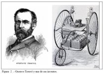
BTW in stalking Gustave around the web I'm seeing lots of mentions with pics like this:
Trouve_Ayrton-Perry.jpg

And this is completely WRONG. The trike pictured was put together by English Professors William Ayrton & John Perry in London in 1882. It's a cool trike, but it's NOT Gustaves! Most of these mixed up references are German-language for some reason. This pic above comes from a Spanish-language doc where the caption reads "Gustave Trouvé and one of his inventions."

Just sayin'

1oCk
 
One more account about Plante cells and how Faure made them viable... from the book "Die magnetelektrischen und dynamoelektrischen Maschinen" by Gustav Glaser-De Cew published in 1884. It details again some of the specs for Plante and Faure cells (this time, badly translated from the original German):
This von Ritter pile can be seen as one of the first secondary electric batteries or electrical accumulator. The credit, however, for the first application of polarizing the electrodes for the construction of an effective and practical battery is due to the French physicist Plante, who in 1859 constructed a secondary battery, the effectiveness of the chemical decomposition of lead oxides.
DeCew_1884Fig.48.jpg
Plante's element (Fig. 48) is made in the following manner. A fairly wide strip of rolled lead is down to another strip of the same size, so that both strips are covered. However, to avoid contact between the strips, you put between the lower and upper two strips about 1 cm. wide and 0'5 cm. thick rubber bands of the same length as the strips of lead, and after having put on the top strips of lead two such rubber bands, they roll the two strips around a wooden cylinder and obtained in this manner after removal of the wooden cylinder in a spiral, in which the two metal strips are completely isolated from each other. To give the system greater strength, the lead coil is held together at one end by gutta-percha braces. The making of the element is accomplished by this lead roll, with two strips of lead poles provided in a cylindrical vessel which is closed with a cover of hard rubber. The cover has openings for the poles and an opening for introducing the electrolyte. The liquid is 10 per cent sulfuric acid-containing water. If one now connects the poles of an cell constructed in this way with the poles of two coupled Bunsen elements and a current can circulate through the Plante cell, is formed in the dilute sulfuric acid on lead peroxide as the anode (Pb02); on the other hand, the cathode lead by the nascent hydrogen is reduced as metallic lead. The latter thus receives a gray granular surface, while the former is provided with a brown covering.

Removed now, after the current of Bunsen's elements has a time can work (it does the same only for so long by the Plante cell circulate to show up at the anode oxygen bubbles), the Bunsen battery and connects if the poles of the plante cell, then a strong polarization current. The oxygen of the peroxide that is powerful moves now to the hydrogen peroxide and sulfuric acid deoxidized, while the released oxygen found in the lead intake, which previously formed the cathode, and now there formed peroxide. The power lasts as long as the cathode receives oxygen. Listening to the current, it may be the conditions to obtain a new current again through new charge by Bunsen elements, and since the discharge may not be performed at once, but in the event you want only after several days, then you have in fact in Plante cells a reservoir of electricity.

This cell is not immediately able to take a big load, but the performance of the cell improves through frequent charge and discharge to an acceptable level. The cell must, as Plante puts it, be "formed", and this "forming" of Plante's cells is a long and arduous process.

The first charge forms only a small amount of peroxide, thus are obtained in the discharge current of only short duration. Only you have to reverse the poles, ie oxidize the previous negative pole and the reducible earlier positive. Now takes the lead strips to the reduced oxygen and forms superoxide at him, while the plate is previously oxidised by the oxygen-free hydrogen. This reversal process must be repeated often according Plante's specification. On the first day you have to charge six to eight times, with a quarter hours at the beginning to load up ascending to an hour, and discharged, then the element is allowed to be charged overnight. On the second day it is discharged and then charged the other way around for two hours, discharged again, then again in the opposite way, and now allows the cell are cycled for eight days. After eight days, it is again, without reversing, charged a few hours, then charged for 14 days allowed to stand, etc. In this way, the element improves more and more, the amount of peroxide formed is larger and the duration of the polarization current increases in consequence. With a well-formed Plante cell a strong platinum wire of 1 mm. diameter can be made to glow for 10 minutes, and a platinum wire of 1/10 mm. glow even for an hour.

The spiral shape of the electrodes gives the Plante cells a very low resistance and a very large electro-motive force, and the cell constructed accordingly is very advantageous. The services of the same cell would undoubtedly have secured a large application in practice, if the "Forming" were not a big obstacle. This "Forming" was the reason that except for galvano purposes Plante cells hardly applied in practice, although the same form a very convenient source of electricity once they are formed.

The credit for making the forming a shorter process belongs to a Frenchman named Faure, who applied to the construction of the cells lead in a powdered form. Its element consists of two strips of lead of 200 mm. Width, 600, respective 400 mm. Length and 1, respective 0.5 mm. thickness, on which he applies a slurry of water mixed with red lead (Pb204) as thick as possible. On the large plate it with 800 gr., the small 700 Gr. Red lead on. To capture the pulpy mass on the metal strip, he puts the same one strip of parchment paper on a felt strip. The whole system is then rolled up just like the Plantes cells and into a vessel (More recently, Faure also used glass vessels. see Figure 49) clad with red lead and felt, to which one pole piece is soldered and thus takes part in the action. The liquid is the same as in the Plante cells, ie, in a ratios of 1:8 or 1:10 diluted sulfuric acid.

If the cell is ready and passing a current through it, it is first formed, as stated by Dr. Aron (E.Z., June 1882), at the outermost layer of red lead a very thin layer of lead dioxide and sulphate of lead, on the one hand, then reduced to lead, while the other, that is pure lead peroxide. But then the underlying layer of red lead is attacked, etc, until by and by a surface formed to include a large charge is capable of.

A two-to three-time charge of the cell is sufficient to be the same for the use to finish, and the layer of red lead on one electrode has then completely transformed into peroxide, while the red lead is on the other electrode of reduced lead.

As for the performance of Faure's batteries, there was up to the beginning of this year very little reliable data, and while on the one hand, the improved Faure Plante battery has seen ridiculous claims, on the other hand, the Faure battery physicists have shown a scientific invention unworthy of this distainful puffery. One of the first professional scholars who endeavored to determine the value of Faure's battery in a conscientious way, was Mr. Frank Geraldy, the results of his in the club with Mr Hospitalier experiments made in the electrical trade journals: published "La Lumiere electrique," and proved that it is almost as powerful as Plante's. Faure's cell of the same weight. The advantage of Faure's cell in contrast to the Plante's however, is that the former almost immediately after he finished preparing for the use, while the latter requires a laborious "Forming."

Watt I thought interesting was how...uh... "rustic" the Faure cell appears that Glaser-De Cew portrayed... sorta like hand-assembled 21st-century lithium packs made in China :lol:

Lock
 
Just still trying to understand watt sort of performance Gustave was getting out of his trike...
...kept a window at l'hôtel de Hollande...
He traveled several times in the Rue de Valois its entire length and as quickly as a good hansom cab. -
That, sir, as briefly as possible, the portrait of electric tricycle, 8 April...
-Gaudet.

...was placed, on the 8th April, on a tricycle...
...recorded a speed of 12km/h.
-Gustave

The tricycle ran for an hour and a half at the speed of a good carriage.
-Popular Science Monthly 1881

...traveled several times in both directions, the Rue de Valois, the speed of a good car. The experiment lasted one hour and a half
-Alexis Clerc


EVerything points to Gustave taking his trike on the road on Tuesday, April 8, 1881...

And riding up and down the Rue de Valois several times over the course of one and a half hours... (on one charge?)

Thing is, Gustave was living and working in downtown Paris at this time and this neighbourhood still exists! (I'm an urban 21st-century North American guy used to having most stuff from decades ago already torn down/replaced/forgotten...)

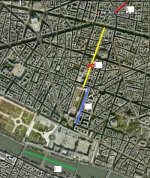
Here's a map of Gustaves travels ie where he worked and played:
Paris_map.jpg

In this map "A" marks "4 rue Cadet"... where apparently Gustave had a "window" at l'hôtel de Hollande (does this mean an apartment?), kinda fun `cause l'Hotel is still there today:
HotelDeHollande.jpg

...and this was only a short walk to rue Vivienne where Gustave had his shop (labeled "B" on the map) watts kinda fun `cause his shop on rue Vivienne is still there today too:
14rueVivienne.jpg

...and if ya believe the reports Gustave only had to motor down rue Vivienne then a small dog-leg to get to Rue de Valois (labeled "C" on the map.)

And Valois, from top to bottom, is 377 meters long. So if Gustave travelled this length "several times" this might have been 1.5 km... 2.5kms...

While Gustave reported "...a speed of 12km/h" this was probably at maximum, as Valois is narrow (today a one-way street) and was probably crowded at the time...

Really just trying to work out watt sort of Whs Gustave was working with, with his six jars of Faure cells running a maybe 20% efficient motor at slow speeds for 90 minutes. :)

More off-topic, but "D" on the map shows the course over which he was running his eboat that summer up/down the Seine... between Pont-Royal and the Ponts des Arts (a pedestrian foot-bridge.) Reports say he was taking guests aboard from the "ponton de tourists" watt were the landing stages along the river banks for riverboats taking tourists for trips on the Seine. One map from 1890 shows the location of the "pontons":
le_ponton_du_Touriste_map.jpg

...and their modern replacements are still there today:
le_ponton_du_Touriste.jpg

Back to ebikes and Gustaves trips up/down the Rue de Valois on April 8... at the very bottom of the street, Valois runs into rue Saint-Honoré and right across the street is the Louvre Museum, but right on the corner of Valois and Saint-Honoré is the famous and infamous Palais Royale, built by Cardinal Richelieu in 1639:
PalaisRoyal2.jpg

And if ya look at the very eastern end of the Palais, the corner at the foot of Valois:
PalaisRoyal1.jpg

That corner of the Palais looks very much like the backdrop for that one image of Gustave motoring around on his trike... :D
file.php

LocK
 
Julien Lefèvre published his book L'électricité à la maison ("Electricity at home") in 1889...

Lots of details about wiring up your home for electric lighting, table-top electric trains for delivering food around the dinner table (not kidding!), wiring up a horses bit to discourage bad behaviour (not kidding!) but also touched on motors, especially for transportation...

'électricité_à_la_maison_1889Fig163.jpg
Trouvé motor. - The engine Deprez is electro-magnetic; that of M.Trouve is electro-dynamic instead. The coil F is still a Siemens type; it rotates between two pole pieces carved in the shape of an ellipsoid, and animated by an electro-magnet placed at the bottom of the unit. Figure 163 shows the motor placed on a cast iron foot that can be removed at will. The motor is 25 centimeters long by 15 wide and 20 high: it can produce 3 kilogrammetres. It can be used to operate a sewing machine or any other small device like that. It is often used to turn static electricity machines intended for medical purposes.

Not sure I have seen these specific dimensions for Gustaves motor given before...


Electric Locomotion. - One of the most interesting uses of electric motors, one that has occupied most inventors, is the traction of vehicles of any kind. We understand how easy it would be advantageous to have a car you could wish to start or stop using a simple switch. But we must admit that so far the results obtained in this way are not very satisfactory. The fact is that the issue of choosing a generator is particularly difficult here, because in general it should be placed on the vehicle itself, and should therefore join the other light qualities that are always necessary such as convenience and economy.

The result of these difficulties that we currently do not have a satisfactory solution for the general case, and electricity was applied only luxury vehicles such as bicycles or canoes, or in cases where it offers special benefits like balloons.
'électricité_à_la_maison_1889Fig164.jpg
Some manufacturers have devised models of electric tricycle - it's usually the batteries that give this preference. They are arranged on a shelf below the seat (Fig. 164) and operate a motor underneath the seat. This motor drives one of the two large wheels, the left, through a pinion and a toothed wheel. A switch at hand to stop the tricycle, to start or change as needed the number of batteries inserted in the circuit. Finally the batteries also provide evening light and operate an incandescent lamp equipped with a reflector at the front.

Funny... Lefèvre mentions quite a few of Gustaves inventions but is silent about his etrike, and chose to illustrate etrikes showing a design looking almost identical to Ayrton and Perrys English etrike design from 1882...


Electric canoes. - It is with boats that was attempted one of the first applications of electric motors. In 1839, physicist Jacobi tried to move an electric boat on the Neva. Despite this attempt, the question remained stationary for a long time. New tests have taken place in recent years, and as this is an application of luxury, in which the expense is a secondary issue, it is possible to obtain good results.

And M.Trouve has applied to power the motor boats that we have described above. As a generator, he gave preference to batteries, which are now lighter than secondary batteries, and can accomplish longer trips, carrying with him the salts necessary to replenish the liquid, such a provision chromic salt, that is dissolved, when using them, with water drawn from the River. M.Trouve used his high volume bichromate pile described above. The secondary batteries on the other hand would not make much away from the point of departure because of the need to recharge. It employs a number of batteries more or less, depending on the force that wants to produce.
'électricité_à_la_maison_1889Fig165.jpg
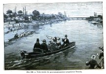
The motor is mounted on the head of the rudder (Fig. 165) and is joined to the battery positioned at will in the front or middle of the boat, with two flexible conductors strong enough to serve at the same time to operate the rudder. The motor drives a propeller attached to the bottom of the rudder. It follows from this provision that, when pulling on a flexible conductor a little the rudder and propeller move together, acting laterally on the boat and helps a lot to turn because the boat can easily turn in a small space. The use of the rudder motor offers yet another advantage in that you can easily place it on any boat without any change to the existing body so nothing is easier than to remove completely the electrical apparatus if you want to make the boat's former system of locomotion, sail or oars. Figure 166 shows the appearance of a boat with the rudder-propeller-motor speed and racing with other boats manned by several oarsmen. Bichromate batteries are placed in the middle, in front of the helmsman.
'électricité_à_la_maison_1889Fig166.jpg
Since the first trials, which date from 1881, M.Trouve slightly modified his system and replaced, for the heavier boats, his original motor with a small motor like Gramme, shown at the bottom of the figure 167. The induction bobbin of this motor is formed by a soft iron core, consisting of thin strips of sheet iron, 0.2mm thick, whose turns are separated by paper. The two electro-magnets constituting the inductors wind concentrically around the armature, the space between the two parts as small as possible, to give its maximum magnetic field intensity. A motor of this type weighing 8kg gives a force of half a horse. This proportion is still increasing with power, because a 10 horsepower engine weighs only 100 kilograms.
View attachment 2
This motor is always placed on the rudder and connected to the propeller in the same way. The batteries are installed amidships in the widest and deepest part. To the right of the helmsman is fixed a switch to stop the boat or to go forward or backward at will. This simple little device consists of six metal brackets attached to an insulating plate: whose ends are connected to the motor terminals and battery. Those in the middle supporting a movable lever whose end can move at will touch the squares in front or rear of those, which closes the current and made to move the boat forward or backward. The operation of the lever is reminiscent of the lever for controlling steam engines.

For shallow rivers and weeds for much of the summer, you can use a tapered auger for the propeller.

We may add that the electric canoe of M.Trouve has a signal driven also by electricity (Fig. 168). This small device consists of an electro-motor D to four vains placed inside a soft iron circular frame A with four protrusions. The vains are attracted to these four projections when the current flows and continue their movement because of the momentum when the power is interrupted. The current comes from the brush and the switch E F, placed at the bottom of the axis of rotation. The motor drives in motion a mobile disk C with holes and topped by a fixed disk B which openings are made in opposite directions. The entire unit is housed at the back of a horn designed to enhance the sound and is mounted on an articulated foot. When the current is switched on, the rotation of movable disk produces a blaring sound that rises rapidly and remains at a high note, shrill and very strong, easy to distinguish from any other signal.
'électricité_à_la_maison_1889Fig168.jpg
The boat of Figure 167 is provided instead of a siren A an air horn that operates using a foot bellows S under the seat of the rower, this signal can even be concealed in a handle of a cane or in a small box in the shape and size of a watch. It is intended for boats with no electric motor or electrical generator.

Finally when a canoe contains batteries for an electric drive motor, it is obvious that we can also use it in the evening for lighting, with the provision that we have described above (Fig. 88).
'électricité_à_la_maison_1889Fig88.jpg

COOL electric horn Gustave! ...wonder how it's sound on an etrike? :twisted:

Haven't paid too much attention to Eureka, Gustaves second boat as she launched in `82 and this is the first images I've seen of her "guts". Obviously Gustave was re-thinking his "mini-motor" designs for larger vehicles (vessels.) Vaucanson chain gone. Journal(?) bearings with lub reservoirs... and not sure but looks like possibly carbon brushes...

Nice to see his Fwd-Off-Reverse switch too... Suspect he had a similar on-off blade switch mounted on his trike. REALLY nice to see the image of both boats together at night with electric lights!

BTW, Gustave was a bit of a joker too... "Eureka" comes from the Greek "I have found (it)"... and Gustaves last name "Trouvé" is also the French word for "found"... makes it a real PITA though, searching any French-language docs etc for the word "trouve" as the word is... found, EVerywhere...

Lock
 
This might be the clearest explanation I've found so far for how the Faure cells were assembled. Published three years after 1881, and relating multi-plate battery construction, but the details about the order that the layers are laminated together is pretty clear:

From "Dynamo-Electricity: Its Generation, Application, Transmission, Storage and Measurement." by George B.Prescott, 1884

CHAPTER IX.
THE ELECTRICAL STORAGE OF POWER.

The storage of electricity by means of electric accumulators, which has recently played so important a part in the transmission of electric energy, is not an entirely new conception. The hydrogen gas battery suggested by Sir William Grove, in 1841, realized in the most perfect manner the conception of storage, although the power obtained from it was exceedingly slight. This battery was made as follows: Into the two outer necks of a three necked bottle two glass tubes were fitted, each of which was open below, and a platinum wire entered them hermetically above, to which a long strip of platinum was soldered, extending nearly to the bottom of the tube. Little cups, containing mercury, were attached to the upper end of these wires. The bottle was filled with slightly acidulated water, and the poles of a galvanic battery were placed in the little cups. Water was thereby decomposed; oxygen forming in one tube and hydrogen in the other. When the battery wires were removed, no change took place till metallic connection was established between the cups, when oxygen and hydrogen gradually disappeared, attended by an electric current, which passed from the oxygen to the hydrogen. When several of these were put together in a battery, the connection being always oxygen to hydrogen, they could decompose water. The most important fact illustrated by this battery was that the oxygen and hydrogen, liberated by galvanic agency, when left to themselves, produced a current the opposite to that which separated them. When the poles of the decomposing battery were in the mercury cups, hydrogen was given off at the —, and oxygen at the + pole; and as opposite electricities attract, it is manifest that the hydrogen in this action was +, and the oxygen —. When two gases formed by means of the platinum plates, a galvanic pair by themselves, the current proceeded from the + to the — within the liquid, and the reverse way between the poles, which was the opposite of the direction of the original current. It is manifest, therefore, that where oxygen or hydrogen is set free at any point in a galvanic circuit, they will tend to send a counter current This tendency is called galvanic polarization.

Sir William Siemens, in 1858, constructed a battery of considerable power by substituting porous carbon or platinum, impregnating the same with a precipitate of lead peroxidized by a charging current. At that time, however, little practical importance was attached to the subject, and even when Plante, in 1860, produced his secondary battery, composed of lead plates peroxidized by a charging current, little more than scientific curiosity was excited. It is only since the electro dynamic motor has become an accomplished fact that the importance of this mode of storing energy has become of practical importance, and great credit is due to Faure, Kabath, Volckman and others for putting this valuable addition to practical science into available form.
Dynamo-Electricity_1884Fig488.jpg
View attachment 1
Dynamo-Electricity_1884Fig490.jpg
Fig. 488 shows a single pile of Faure battery operating a small electric motor. Fig. 489 shows the method of combining the plates. Fig. 490 shows a battery arranged with a commutator for combining the elements for tension or quantity. The plates are of pure lead foil, having a width of 7 inches, a height of 7 1/8 inches, with an ear projecting from the top 1 1/2 inches wide and 3 inches high. The total effective surface on both sides and edges of each plate is 100 square inches. These secondary elements were constructed as follows:

After cutting out a sufficient number of lead plates, pieces of Canton flannel, 15 inches long and 7 1/2 inches wide, were cut, together with as many sheets of blotting paper, 7 1/2 inches square, as there were lead plates. A thick paint of red lead was then prepared by mixing the dry pigment with water containing one tenth of sulphuric acid. This paint had a consistency of paste, and was applied thickly to one side of the sheet of lead. The Canton flannel having been painted to within one quarter inch of its edges on the nap side, the lead was laid, painted side down, upon the painted Canton flannel, when the other side of the lead was painted and the cloth was folded over the lead,completely enveloping it, with the exception of the ear at the top, and projecting about one quarter inch beyond the edges of the lead. The lead with its envelope was then laid upon a level board, and another plate was prepared in the same manner and placed over the first, with an intervening layer of blotting paper, and with the ear placed opposite the ear of the first. Other lead plates were added in the same way, with the interposed sheet of blotting paper and with the ears alternating in position, as indicated in fig. 489. When ten plates had been placed together in this manner they were clamped together, and the ears were passed through a slit in the wooden cover of the containing cell and bent down upon the top of the cover, as shown in fig. 488. They were then pierced and traversed by the screw of a binding post which enters the wood. In this way each pole of the element was furnished with a binding post, and at the same time firmly secured to the cover. The cell was then filled with acidulated water — water 10 parts, sulphuric acid 1 part — and after the cloth and blotting paper had become saturated the element was connected with a dynamo electric machine. One element of ten plates, after receiving the current from the dynamo for ten minutes, operated the small motor, shown in fig. 488, three hours, and another ten minutes' application of the current from the dynamo charged it so that after eighteen hours of rest it yielded a current which was apparently as strong as when it was first charged on the previous day; but a time test proved that it was incapable of running the motor for quite so long a time as when the current is used soon after storing.

"Canton" flannel refers to Canton, China and just means cotton flannel cloth, "fluffy" one side. Other descriptions have said felt... Thinking flannel is the more accurate description, as the nape helped hold the red lead paste to the cloth.

Nice to see a series/parallel switch illustrated again

tks
Lock
 
Found another description of the Faure cells, published in "Electricity In The Service Of Man" by Dr. Alfred Ritter von Urbanitzky in 1886...
Faure's Secondary Battery.— Of those elements in which the process of charging is shortened, we have to name in the first place that constructed by Faure, which has attracted much attention and has met with considerable success. It consists of two leaden strips, one of them 600 millimetres long by 1 millimetre thick, and the other 400 millimetres long by 0.5 millimetre thick. It is manifest that the "storage capacity" of such a battery will depend largely upon the thickness of the layers of dioxide and of spongy metallic lead, which are formed on its plates, for the thicker these layers the more chemical action will they develop in being reduced to sulphate, and the more chemical action will they absorb in being changed back again into oxide and metal respectively. Hence the repeated reversed charging employed by Plante in preparing his cells.
ElectricityInTheServiceOfMan_1886Fig417.jpg
A very simple and ingenious method of saving the loss of time and energy involved in this preparation is the characteristic feature of the element devised by M. Camille Faure. He coats both plates before rolling them up with a paste of red oxide of lead (minium), made into a paste by diluted sulphuric acid. The large plate receives 800, the small plate 400 grammes. The minium is then covered with parchment, and the whole covered over with felt. It is placed in a cylindrical leaden vessel, having its inside coated with minium and felt. Such an element weighs 8,500 grammes without the liquid. The form which Reynier has given to the Faure element is shown in Fig. 417. The leaden vessel is replaced by a glass cylinder, and the felt by a texture which is not destroyed so quickly. As soon as the plates coated with minium are immersed in the diluted sulphuric acid, the minium is converted into lead dioxide and lead sulphate. The current has now only to complete the formation of lead dioxide on the one plate, and to reduce the compounds of lead on the other. According to Uppenborn, a Faure's element has an E.M.F. of two volts and weighs 25 kilogrammes. With three Siemens' machines (model D2) 150 elements can be charged in ten hours; if left unused they lose 1.5 to 2 per cent. per day.


On the first action of the charging current, the sulphate of lead on one plate is reduced to a sponge of metallic lead, while that on the other is oxidised into peroxide. This is the only difference between the "secondary battery" of Plante and the "storage battery " of Faure. Both operate on the same principle and in the same way, with probably some considerable improvement in efficiency, i.e. capacity, in the Faure arrangement. Both batteries are frequently made in the form of numerous flat plates covered with some woven fabric, and packed near together in a rectangular box filled with dilute acid. The sole novelty in the Faure device is in the use of the porous coating of decomposable substance, by which a thick layer of active material can readily be obtained on both plates of the battery. The Faure cells as they are now constructed for industrial use are rectangular in shape, and are arranged in rectangular boxes of wood impregnated and heavily coated with an asphalte varnish, which enables them to withstand the action of the acid solution which fills them. The weight of a single cell of such a battery is about ninety to one hundred pounds.

The great interest which they have excited at the present time arises largely from two causes: first, the enormous improvement in dynamo-electric machines, by reason of which electric currents can be supplied at a small fraction of what they used to cost when they were obtained only from galvanic batteries; and secondly, the great need developed in the attempts to apply the cheap electricity furnished by dynamo machines to various uses, for some means of storing the electric force either actually or practically.

In order that this desired result should be obtained in a way commercially valuable, several conditions must be fulfilled: (1) The storage must not involve any great loss of energy in the charging; (2) the stored energy should be retained with little loss; (3) the cost of the storage apparatus should be moderate; (4) the apparatus should be within moderate limits of bulk and weight; and (5) it should be enduring, and not wear out so as to require frequent replacement.

The most interesting tests of the Faure battery, with a view of determining in how far it fulfilled these conditions, were made at the Conservatoire des Arts et Metiers in Paris, by a committee of which M.Tresca was president, and MM. Allard, Le Blanc, Jubert, and Pottier were members. An extensive extract from the report of this committee to the French Academy will be found in the Telegraph Journal and Electrical Review, of London, for March 18, 1882, vol. x., p. 196.

Passing by all details of the experiments, we will only note the general facts and results. The battery experimented upon consisted of 35 cells weighing about 95 pounds each, or in all 3,325 pounds, say 1 1/2 tons. It was charged by a Siemens dynamo-electric machine, which absorbed the mechanical energy of 1.558 horse-power during 22 hours 45 minutes, which would be equal to one horse-power for 35 hours 26 minutes, or in foot-pounds 70,158,000. Of this mechanical energy 34 per cent. was expended in useless work in the machine and battery during the operation of charging, and 66 per cent. was stored as chemical energy in the battery. Of this stored energy, 60 per cent. was recovered as electric energy. This would amount to about 27,782,700 foot-pounds, or one horse-power for 14 hours 4 minutes. In other words, the actual work of one horse for 35 1/2 hours, after being stored in 1 1/2 tons of battery, could be recovered to the extent of about 14 hours' work of one horse, or the equivalent of the same in electric or other energy. Thus, Mr. Edison's 16-candle electric lamps require about one-sixth of a horse-power each, and therefore six of them could be run for 14 hours with the energy stored in this battery as above stated. Mr. Edison's smaller lamps, which give about eight candles each, or the same light as an ordinary German student's lamp, require but half as much power, and thus six of them could be run for 28 hours by this same battery.

This is, of course, not a high degree of efficiency; but, as the above-named committee remark in their report, "In many cases the loss would be fully counterbalanced by the advantage of having at hand and entirely at one's disposal so abundant a source of electricity."

The occasion of the losses experienced in the storage battery, and also the exact character of the actions, chemical and electrical, which go on in it, are very fully developed in a paper on "The Chemistry of the Plante and Faure Accumulators," by J.H.Gladstone and Alfred Tribe, in Nature, of January 25 and March 16, 1882. The main sources of loss there shown are, first, local action between the negative lead plate and the peroxide of lead deposited upon it; and second, the resistance of the oxide and sulphate to the passage of the current, by reason of which energy is lost by being converted into useless heat in the battery both at charging and discharging.

By so regulating the discharge of the battery as to reduce this loss, and by giving seasons of repose in which the battery recovers some of its deterioration, Messrs. Ayrton and Perry succeeded in recovering 82 per cent. of the power put into one of these batteries. A single cell, weighing 81 pounds without the dilute acid, yielded, in three discharges of six hours on three successive days, an electric current whose total energy was 1,440,000 foot-pounds, which represents about one horse-power exerted for about three-quarters of an hour. This is almost double the efficiency per weight of battery shown by the French experiments, and the recovery of 82 in place of 60 per cent. of the stored energy would indicate a much greater efficiency in this respect also.

Experiments in using the Faure battery for industrial purposes have already been made in various directions. It has been employed to run street cars and other vehicles (including even velocipedes), to propel boats, to work sewing machines and others requiring a small amount of power, to illuminate houses and single rooms, and also steamers and railway carriages. As yet it has only been shown to be economically valuable where peculiar conditions protect it from competition with other means of effecting the same results more directly. Thus it has been used in France at the establishment of M.Duchesne-Fournet, where linen cloth is bleached by exposure to sunlight on bleaching-greens, to run a train carrying out the cloth from the factory to the green, and to wind in the cloth from the green after it has been bleached. An ordinary steam engine could not be used in this case on account of its smoke and cinders. Again, in railway cars it may be more convenient to use a Faure battery than to have a dynamo-electric machine, either run by a special engine or by the motion of the train. The latter would of course be impracticable without some storage arrangement to provide a light when the train stopped.

Indeed, as a regulator of electric currents, to equalise them, or bridge over brief interruptions of the generating machines, a storage battery would seem to have a wide application.

As is well known, a number of these Faure batteries were recently used to maintain four incandescent lights when required on the steamer Labrador, during her passage to New York.
ElectricityInTheServiceOfMan_1886Fig418.jpg
Modifications of the Faure Element.—To give the lead plates a loose surface, G. Schulze, of Strasburg, covers them with powdered sulphur, and then heats them. If now the plates be immersed in dilute sulphuric acid, and the current allowed to pass, at one plate the sulphur will combine with the hydrogen and escape as sulphuretted hydrogen, leaving spongy lead behind, whilst at the other plate lead sulphate and lead dioxide will be formed. The elements consist of plates 23 centimetres high, 12 centimetres wide, and 0.5 millimetre thick, which are suspended and connected as shown in Fig. 418. The lead of an accumulator consisting of thirty plates weighs 8 kilogrammes. The total weight, including the fluid, is 10.5 kilogrammes. When charged, the element possesses a resistance of 0.005 ohm, which is increased during the discharge to 0.015 ohm, by an E.M.F. of 2.15 volts. De Calo uses for his secondary elements plates consisting of spongy lead coated with minium and placed in little sacks. Kornbluh uses lead wire gauze coated with minium; ten plates of 6 millimetres thickness are joined to form one element. The secondary element constructed by Boucher is shown in Figs. 419 and 420. The negative electrode here consists of sheet zinc z bent into a U-shape. Within it is suspended the waved leaden plate P, coated with litharge; and, to prevent contact, parchment F is wrapped round it. The several plates are fastened to a frame which can be moved up and down. Each element receives 300 grammes of zinc sulphate, and separates zinc out during the charge, forming lead dioxide at the lead plate. The charged element then consists of lead dioxide, zinc, and sulphuric acid. If the plates were not taken out of the liquid, the zinc would again dissolve in the sulphuric acid; to prevent this the plates are arranged as shown in the figure. During the discharge zinc sulphate is formed in the element, and at the same time the lead dioxide is reduced. According to Bottcher, the element furnishes a current after discharge, on account of the galvanic element, consisting of lead, zinc, and zinc sulphate; this current cannot, however, be of very long duration, as polarisation will quickly set in. For practical purposes the form would have to be altered.
ElectricityInTheServiceOfMan_1886Fig419.jpg

So turns out (according to Ritter von Urbanitzky) the "Faure" cells illustrated so far are actually Reynier varients, where Reynier had chucked the original design that included the case/jar itself lined with lead as one of the elements in the cell. Thinking that for Faure cells, Year One, Gustaves cells (jars?) might not have looked like these clear bottles after all.

Detail about the amounts of red lead differ also. Where Glaser-De Cew reported 800gr on the large plate and 700gr. on the small plate, here Ritter von Urbanitzky says "The large plate receives 800, the small plate 400 grammes."

Hmmmm... I wonder watt proportions are closer to the truth... Faures patent is completely silent on these details about the thickness of the plates and the relative portions of minium.

Lock
 
I'm going to pick up some lead and minium and flannel etc this week and roll up a few cells...

Figure I can find jars in a restaurant or lab supplies shop, so want to do some roll-ups first to make sure I know the dimensions I need for the jars. Found a local gal that makes beautiful stuff outta wood to make me a case for the battery and need to give her the exact dimensions of the jars.

Problem I'm having is the ratios of red lead to lead I have been reading are all over the map...

From that July 9, 1881 issue of Scientific American magazine:
The current number of Le Journal Universel d'Électricité contains, says Engineering, a very ably written article by M. Frank Geraldy upon the Faure secondary battery,

Two sheets of lead are taken 7.87 inches wide; one of these plates is 23.62 in. long, and 0.04 in. thick; the other is 15.75 inches long and 0.02 inch thick. Each plate is covered on both faces with a layer of red lead reduced to a paste by water, 1.76 lb. being spread over the larger plate, and 1.54 lb. over the smaller.

This all works out to:
1.76 lbs of red lead for 3.26 lb plate so 1: 1.85 ratio
1.54 lbs of red lead for 1.09 lb plate so 1.41: 1 ratio

Or an overall ratio of 1: 1.318 ratio, red lead to lead sheet.

S.P.Thompson reported in November 1881, 25lbs of red lead to about 17lbs of lead...
So a ratio of 1.47: 1, red lead to lead sheet...

Then ya got Faure himself. Haven't found these details in his own words yet, but:
M.N.de Kabath wrote in the May 1, 1882 edition of " L'Electricien" about his own "Kabath" flavour of Faure cells, but in the article he quoted a letter that Faure wrote to M. Hospitalier:—
"I have paid great attention to the electro-chemical theory of my battery, and by repeated analyses of the substance of the active layers of the electrodes at different times of the charge and discharge, always, allowing for the current which had passed between two experiments, I believe that I have been able to make out that the effect which is first observed is the carrying of a certain amount of oxygen from one plate to the other, and vice versa, in accordance with the electro-chemical equivalents; and that, for example, during the discharge, the reduced lead was converted into Pb2O1, whilst the Pb2O4 was changed into Pb2O3. But I have remarked that this only took place in a small proportion to the total thickness of the layers, about 10 per cent. I attribute this to the resistance opposed by a semisolid substance, such as the oxides of lead, to the transmission of the electrolytic action; in fact, a considerable portion of the mass is unacted upon."
Not sure I have quoted Camilles lead-oxide formulas correctly (original scan of the article was very bad) but the point is that Camille was aware that as much as 90% of the oxides weren't doing any work at all... Perhaps in those early daze he had been buttering on the red lead way to thick.

So I'm just gonna go with the 2 lb/sq.ft. lead sheets (1/32" thick), and roll a few cells each with different ratios of red lead to lead and see how they each perform... or should I say which one performs slightly less horribly than the rest... :lol:

Lock
 
The January 1882 monthly journal "The Electrician" has another article about Gustaves boat:
THE ELECTRIC BOAT.

THE first trial of an electric boat was made on the Neva as far back as 1839. The idea originated with Jacobi, who was supported by the Russian government; but the experiment was only partially successful, and was abandoned until quite recently. The motor employed by Jacobi was excessively heavy, and, although it was furnished with 128 Grove piles, it supplied a comparatively feeble motive power. M.G.Trouve, who is a well-known maker of scientific instruments, has built a small electric boat, which was tried last summer on the Seine, near the Pont Royal, and which excited great curiosity.

The electric motor was applied to a small yawl, Le Telephone. Two electric motors, placed at the helm, communicated the power by means of a Vaucanson, or band chain, to a three-branched screw. The gearing is greatly simplified by this ingenious arrangement, while steering is facilitated; for a turn of the helm causes the axis of the screw to turn at the same time, while the oblique action of the latter assists the rotatory motion. The electric current is conveyed to the motor by two flexible metallic cords, which are covered with cotton. They serve at the same time to work the helm. Handles are attached in the form of a commutator, so that the electric current can be interrupted or restored at will. The two motors are small dynamo-electric machines, with Siemens coils and Trouve's modification. They are absolutely independent of each other, and act together, or separately, according to the rate of speed required. Two bichromate of potash piles, with large surface and six elements each, feed the motors. The weight of the boat, with the piles, motors, and three passengers, was 350 kilos. It ascended the Seine at the rate of one meter per second, but came down the current with a speed of two meters; the rate of the current itself being about 20 centimeters. But, although the whole device is very ingenious, and the experiments interesting, it must not be concluded that the problem of running pleasure boats has been solved.
Even supposing that Trouve's electro-motor gives a satisfactory product (and experiments now making will soon enlighten us on this point), yet it is evidently radically wrong in the electric source itself. The bichromate pile is very active for a few moments, but is then rapidly polarized. The experiments lasted only a few minutes in each case, so that the elements had to be taken out of the liquid at once to facilitate depolarization. We question very much whether an equable and continuous power can be obtained during several consecutive hours. The electric boat is at present only another interesting exhibit of the inexhaustible resources and applications of electricity. Further experiments will be made in the Bois de Boulogne with a small boat specially built by M.Trouve; but it is only when a strong, cheap, and constant pile will be found that the invention will be of practical utility. To discover such a pile, however, is the great problem in electricity.

So here's another article that mentions Gustave shutting off the power to one of the two rotors in his twin model... Yet all the illustrations don't seem to show how he was doing this *except* that he has TWO inline switches built into the wires/tiller ropes. Everything LOOKS like the two batts were paralleled together at or before the switches, but maybe not. If the wires in the tiller ropes between the switches and the motors continued as two conductors, one switch might have shut off one motor-battery pairing, and the other switch shut off the other motor-batt combo. Otherwise, why bother with two switches in the same circuit???

Still finding it hard to believe that one rotor switched off but geared to the other so that it continues to spin while "dead" is a good thing...

Lock
 
One more data point on minium content...
The Minutes of proceedings of the Institution of Civil Engineers from 1882 has a section called "Foreign Abstracts"

Experiments made on a Faure Secondary Battery. By Messrs. Allard, Le Blanc, Joubert, Potier, and Tresca.

(Comptes rendus de l'Academie des Sciences, vol. xciv., 1882, p. 600.)

The experiments were made at the Conservatoire des Arts et Metiers, Paris, upon a battery of thirty-five elements, having spiral-shaped electrodes of lead, covered with minium at the rate of 10 kilograms per square metre; the liquid was distilled water with a tenth of its weight of pure sulphuric acid added; each element weighed 43.7 kilograms, with the liquid included. A Siemens dynamo was used for charging, a sort of voltameter with carbon electrodes being interposed, in which the resistance was modified by changing the quantity or nature of the liquid; by this means the current was kept between two and three amperes. The main object of the experiments was to measure the mechanical work expended, and the quantity of electricity, stored during the charge, the quantity of electricity given out, and the mechanical work performed during the discharge. The mechanical work was measured by means of Messrs. Easton and Anderson's dynamometer, and as the current was employed on a series of incandescent lights, the luminous intensity was measured by means of a Foucault photometer. The total and exciting currents were measured by means of a Deprez galvanometer, the charging current by means of a Siemens electro-dynamometer, and the difference of potential between the two poles of the battery by means of a dial electrometer according to Mr.Joubert's method; the indications were read every quarter of an hour. Tables of results are given, from which the following conclusions may be derived :—There was only a loss of 10 per cent. between the quantity of current charged and discharged, the mechanical work performed was 40 per cent. of that employed in charging the battery, and 60 per cent. of that stored in it, the ratio of potential of charge to discharge being as 3:2. The best results are obtained by charging with the weakest possible current, and prolonging the duration of the charge. The resistance of the battery is found to be sensibly weaker during the discharge than during the charge. Charging the battery took the equivalent of a horse power for thirty-six hours, of which two-thirds was stored, and two-fifths finally given out. The value of the arrangement is the storing of electricity that might otherwise be lost or that cannot be immediately utilised. E.F.B.


...10 kilograms per square metre...

Red lead weighs 8.3g/cm3
so 10kg = 1204.819277 cm3
1204.819277cm3 spread over 1m2 (10,000cm2) = 0.12048cm or 1.2mm thick

Lock
 
BTW, in that same January 1882 issue of the monthly journal "The Electrician" that has the article on Gustaves boat, the editors also mention they have built their own lab for assembling and testing Plante cells and other electrical apparatus. Kinda cool `cause it illustrates watt must have been state-of-the-art battery assembly and charging by late 1881:

THE LABORATORY OF "L'ELECTRICIEN."

CONSTRUCTION OF THE SECONDARY BATTERIES OF GASTEN PLANTE.

THE physical laboratory of which it is our purpose to give a description is situated in the "rue de Rueard," Paris, at the end of a courtyard.

This laboratory, founded by the managers of the journal L'Electricien, is especially designed for scientific and industrial researches.

During the past few months the construction of secondary batteries of Mr. G.Plante, have been studied, their importance becoming more and more apparent as the applications of electricity are augmented.

General attention having been directed to these batteries, it is thought that our readers will peruse with interest a few details of their construction.

The manufacture of secondary batteries comprises, 1st. Their construction, properly speaking. 2d. Their charging under the action of an electric current.

Our first figure represents the laboratory proper, where the batteries are made. They are begun and finished in series of sixty, each weighing about 10 kilogrammes.
Electrician_1882JanLab.jpg
They are constructed according to instructions given by Mr.G.Plante, in his Researches on Electricity, and according to the verbal instructions of this celebrated electrician.

These batteries are composed of a cylindrical glass jar in which are enclosed two plates which are wound spirally upon each other, and separated by means of a thin sheet of caoutchouc. The element is then filled up with water acidulated with 1/10 of pure sulphuric acid.

The battery thus formed is closed with a cork covered with matsic, and surmounted by a small yoke of wood permanently fastened, and into which are inserted two connections of copper which are attached to the positive and negative sheets of lead.

There are thus constructed in the laboratory of L'Electricien secondary couples of very light weight, of very thin sheets of lead and of large surface, apparently giving very surprising results, but of which we are unable to speak further until experiments of measurement have been made in an exact manner.

Accumulators of different systems are also studied here.

The secondary batteries being constructed are then charged by means of an electric current.

Our second figure represents the arrangement adopted in the laboratory of L'Electricien to furnish a current of electricity under the necessary practical conditions.
Electrician_1882JanLab2.jpg
The current is produced by means of two Gramme machines operated by an Otto gas engine of four horsepower. The first Gramme machine, that seen to the right, is one of the Class A, which is used in the charging and formation of the secondary batteries.

At the side of this machine is one giving alternating currents and which is used for different experiments. The first Gramme machine is operated through induced currents, but a smaller machine may be employed for this object, serving thus as an exciter.

The charging of the Plante secondary battery may be effected under the influence of currents furnished by the Gramme machine, but as the currents are very intense, it is necessary that a special arrangement should be made and that resistances should be interposed in the circuit.

There may thus be charged at a time a large number of elements, either arranged for quantity or intensity.

The arrangements which we have endeavored to succinctly describe may serve as the model for a workshop for the construction of the secondary batteries which are now soon to emerge from the domain of experimental science, to take a place in that of industry and practice.

The laboratory of L'Electricien comprises also three other parts which we have thonght unnecessary to represent by engravings. There are executed in them various experiments; notably the measurement of electro-motors and incandescent lamps.

The French and American engineers work here regularly, having at their disposal water, gas, electro-motive force, that is to say all the elements necessary to ensure the success of their researches.

The laboratory of L'Electricien is an example too rare with us. A beautiful scientific undertaking founded by private enterprise; we have thought it our duty to bring it to the attention of our readers, hoping that we may be able to present them the work which may be therein executed.

I dunno... if I were visiting their lab from North America, think I'd be having a hard time getting any work done in "Gay Paris"... :)

loCk
 
Nice mini-bio of Gustave... from "The Electrician's Directory with Handbook for 1885"

TROUVE, Gustave. Fabricant d'instruments de precision, ingenieur construeteur, brevete, Laureat de la Faculte de Medecine de Paris, Membre Laureat de l'Academie Nationale Agricole, Manufacturiere et Commerciale, de Association Scientifique de France et de la Societe d'Encouragement pour l'Industrie Nationale, Chevalier de la Legion d'Honneur; born at Lahaye, Descartes, January 1st, 1839.

During his early years M.Trouve manifested a decided predilection for the applied sciences, and studied with great assiduity; his only amusement being the construction of various kinds of miniature telegraphic apparatus. At the age of seven years he contrived and finished a steam engine, which, despite its Lilliputian proportions, worked with precision. In the College de Chenon, where he commenced his actual studies, M.Trouve displayed an especial aptitude for the mathematical and mechanical sciences, and when he had passed through a course of instruction at the establishment we have named he quitted his native town for the purpose of entering l'Ecole des Arts et Metiers D'Angers; and afterwards went, at the age of twenty, to Paris, in order that he might further perfect himself. In 1866 M.Trouve established his workshop for the manufacture of instruments of precision, and soon entered into relations with the principal physicians of Paris, for one of whom he designed and executed, in three days, the instrument known as "d'explorateur-extracteur-electrique," a contrivance for localising and facilitating the extraction of projectiles from the human body. He has obtained for his apparatus honourable mention at the Paris Exhibition of 1867; silver medal of the Societe d'Encouragement in 1870; progress medal at the Exhibition of Vienna, 1873; gold medal at the Academie Nationale, 1875; Barbier prize of the Faculte de Medicine in 1875; gold medal at the Universal Exhibition of Paris, 1875; diplome d'honneur at the Academie Nationale, 1879, &c, independently of many other gold and silver medals which he has at different times been awarded for home and foreign exhibits. The inventions and other works of M.Trouve are almost innumerable; among the principal of them, however, may be mentioned "the double movement electro-spherical motor," which demonstrated the law of Newton that the action is equal to the reaction, and the force to the resistance, and which is employed at the present time to demonstrate the reactions in Professor Crookes' radiometer; the reversible hermetic battery (1865), presented to the Academie des Sciences in December, 1867, by M. Becquerel; the electric gyroscope (1865); the electro-medical pocket case, presented to the Academic des Sciences, 1867; apparatus for experimentally and immediately determining the best angle of inclination of a helix for any given force (1867); military portable telegraph, presented by the late M.du Moncel to the Societe d'Encouragement in 1872; a constant and continuous cell — said by M.Trouve to be more constant than the Daniell — which was presented by M.Becquerel to the Academie des Sciences in 1873, and to the Academie de Medicine by M.Gavarret in 1874; a dynamo-electric or magneto-electric machine (1875); an electromagnetic apparatus registering the number of its alternations — which placed in evidence the mode of muscular contraction — presented to the Academie des Sciences, (1877); a new electric reversible motor (1880); application of electric motors to pleasure boats (1881); an electric tricycle, travelling 15 kilometres (9.32 miles) per hour (1881); application of the Trouve electric motor to balloons (1881); practical solution of domestic electric lighting (1883); the Trouve universal electric safety lamp (1884), and many others. M.Trouve has endowed science with apparatus of incalculable value. Among the most curious and most useful of his inventions is the electric polyscope, which he perfected in 1869; by its means a thorough diagnosis of the throat, the ear, the eye, or any remote part of man's organisation can easily be made. M.Trouve was named Chevalier of the Legion of Honour by decree of the President of the Republic on the 29th of December, 1881.

BTW, when Gustave died in 1902, he'd cut his thumb with a hand saw... Docs wanted to amputate but Gustave said no, and septicemia got him... :cry:

So EVerybuddy play safe.

Lock
 
Found this as an appendix in the book "Electricity as a Motive Power" by Theodore Achille Louis, Comte du Moncel and Frank Geraldy, August 1883 translation by C.J.Wharton. It talks about Gustaves Bichromate of Potassium cells, but also includes specs on his motors:
Note B.—Some Details Of Trouve's Battery, As Used In His Electric Boat.

Each element of this battery is composed of a plate of zinc placed between two carbons. The dimensions are as follows:—

Total height .24 metre.
Width....... .16 "
Thickness... .005 to .008 metre.

The immersed surface is about .16 metre square.

The carbons are electro-coppered at the upper part, which considerably diminishes the resistance of the battery, gives a good surface for the contacts, and consolidates the carbon, always rather a brittle substance. The zinc plates, heavily amalgamated, have on their upper part a notch, into which is fitted the metal couplings covered with india-rubber, which supports the elements. This allows of ready removal, either for amalgamation or for any other purpose. The exciting liquid contains much more bichromate of potash than ordinary solutions, and it was also found necessary to increase the quantity of sulphuric acid to as much as a fifth, or even a fourth, of the total weight of water. As much as 250 grammes of bichromate per litre of water have in this manner been dissolved, and the constants of each element are, according to M.d'Arsonval:—

Electromotive force E ............ 1.9 volt.
Internal resistance r ............ .08 ohm.
Intensity at moment of insertion 118 amperes.

On joining up a battery of six cells of this description with a one-bobbin Trouve motor, M.d'Arsonval gives the following as the result:—

Work in the brake..... 3.75 kilogrammetres per second.
Current................ 20 amperes.
Zinc expended per hour 144 grammes.

Whence it appears that each gramme of zinc gives by this means 94 kilogrammetres of force. If we add to this 20 per cent. for the work absorbed in the double transmission by gearing and endless chain (the brake not being able to be applied direct on the axis of the motor), we have an effective work of 112 kilogrammetres per gramme of zinc consumed; and it is said that, with motors having several bobbins, this return has been exceeded.

It is also said that this battery, when used in conjunction with a Gramme machine, has been made to furnish for three consecutive hours a force of 14 kilogrammetres per second, and the following is a table of experiments undertaken by M.Trouve :—
Electricity_as_a_motive_power_1883.jpg

Dunno exactly when Gustave published these numbers but this is the first reference I've seen to his using up to eight bobbins in one of his motors...

Staying with his 2 bobbin configuration at 5kg in weight (seems to be the motor most often referenced by Gustave et al) here he ran the motor on 12 bichromate cells - in series I assume - so 22.8V, producing 28,800 kilogram-metres per hour... watt works out to only 78.45W...

This confirms watt LFP calculated earlier from the 7kgm per second Gustave reported to the Academy... except in that report he said he was using only six Plante cells, AFAIK about 12V.

Anyway... having a hard time sourcing pure lead tetroxide... turns out the minium sold these daze as artists pigment is only about 70% Pb3O4 plus impurities, other oxides of lead mostly. But maybe the stuff Gustave etc were rolling up in 1881 wasn't 100% either... dunno.

Lock
 
Hallo,

mein Name ist Franz Haag.
Ich wohne in Deutschland.
Ich baue das 1881 Trouvè Tricycle nach.

ich spreche nur deutsch :(


Mit freundlichen Grüßen

Franz Haag Kfz-Sachverständiger
Wertachstrasse 25
87616 Marktoberdorf
Deutschland
info@franz-haag.de
http://www.franz-haag.de
 
Hallo Franz

Wunderbare Neuigkeiten! Ich hoffe, dieser Thread kann Ihnen gute Dienste leisten! Alle weiteren Details können Sie hinzufügen? Ich denke, Gustave machte seine eigenen Zellen, sondern es ist schwer, genau, welche Variante zu sagen!

Cheers!

Schloss

(Bitte vergib mir meine Google-Übersetzung) :D
 
Willkommener Franz!

Ich hoffe Sie Aufenthalt, weil Verschluss die ganze Hilfe benötigt, die er auf diesem Projekt erhalten kann! Er hat eine große Arbeit als Detektiv erledigt, zu verstehen, welches Trouve entwarf und errichtete, aber es gibt viele Widersprüche und Löcher in den Daten. Ich sehe, dass Sie wünschen, eine Replik von Trouve' zu errichten; s elektrisches trike auch.

Das ganzes Beste, Dave


Welcome Franz!

I hope you stay because Lock needs all the help he can get on this project! He has done a great job as a detective to understand what Trouve designed and built, but there are many contradictions and holes in the data. I see that you desire to build a replica of Trouve's electric trike also.

All the best,
Dave
 
Hallo,

Danke für die Rückmeldungen.

Meine Fragen:
- Existiert schon ein Nachbau des Trouvè Tricycle 1881?
- ist ein Nachbau des Trouvè Tricycle 1881 in Arbeit?

Mit freundlichen Grüßen

Franz
---------------------------------------------------------------

Google Translator:
Hello,

Thanks for the feedback.

My questions are:
- If there is already a replica of the Tricycle Trouvé 1881?
- Is a replica of Trouvé Tricycle 1881 in work?

Sincerely

Franz
 
Back
Top