Replica ebike - 1881

Lock said:
Watt I'm reading about for dynamos and motors circa late 1870's are insulating materials like silk and cotton for wiring, simple paper soaked in paraffin for insulation between winding layers etc, ivory and wood...

Forgot to mention this stuff too `cause it's kinda cool... "Gutta-percha":
http://en.wikipedia.org/wiki/Gutta-percha
Gutta-percha (Palaquium) is a genus of tropical trees native to Southeast Asia and northern Australasia, from Taiwan south to the Malay Peninsula and east to the Solomon Islands. The same term is used to refer to an inelastic natural latex produced from the sap of these trees, particularly from the species Palaquium gutta.

Gutta-percha latex is bioinert, resilient, and is a good electrical insulator due to a high dielectric strength. The wood of many species is also valuable.

Western inventors discovered the properties of gutta-percha latex in 1842, although the local population in its Malayan habitat had used it for a variety of applications for centuries. Allowing this fluid to evaporate and coagulate in the sun produced a latex which could be made flexible again with hot water, but which did not become brittle, unlike unvulcanized rubber already in use.

By 1845, telegraph wires insulated with gutta-percha were being manufactured in the United Kingdom. Gutta-percha served as the insulating material for some of the earliest undersea telegraph cables, including the first transatlantic telegraph cable. Gutta-percha was particularly suitable for this purpose, as it was not attacked by marine plants or animals, a problem which had disabled previous undersea cables. The material was a major constituent of Chatterton's Compound used as an adhesive sealant for telegraph and other electrical cables.

... and the stuff is still available too, as dental supplies:
http://www.alphadental.com/webstore...95_109&zenid=3e79e20850cae4ead8866c5d1aefbe6d

LocK
 
Lock said:
...actually thinkin' I can roll my own cells - literally...

The July 9, 1881 issue of Scientific American magazine had an article "THE FAURE BATTERY - STORED-UP ELECTRICITY." which details the construction pretty well:
The current number of Le Journal Universel d'Électricité contains, says Engineering, a very ably written article by M. Frank Geraldy upon the Faure secondary battery, to which we recently referred. From this article we find the space to make the following extracts: "The posters bearing the words "Power and Light" in enormous letters, are still visible on the walls; the noisy articles that have appeared in certain journals are not yet forgotten; however, the bills are beginning to disappear, the effect of the articles to decrease, excitement is on the wane, and the scientific press can at last be heard. It has, indeed, been difficult to discuss this matter sooner, for it was essentially necessary to have data and information as exact as possible, and these have not been obtained without trouble."

The author then refers briefly to the secondary battery of M. Reynier, and proceeds to describe the Plante battery, which he states to be almost identical with that of M. Faure, M. Plante having, except in one point, long ago anticipated what M. Faure has recently brought forward, and which has been received with so much popular excitement. He then continues: "We will now proceed to the Faure secondary battery. It is protected by two patents dated October 20, 1880, and February 9, 1881, respectively. In these patents M. Faure describes principally those batteries composed of lead plates laid on frames covered with red lead, and protected by leather, attached by means of lead rivets, an arrangement similar to the rectangular balteries of M. Plante. The actual batteries are not so made, being constructed as follows: Two sheets of lead are taken 7.87 inches wide; one of these plates is 23.62 in. long, and 0.04 in. thick; the other is 15.75 inches long and 0.02 inch thick. Each plate is covered on both faces with a layer of red lead reduced to a paste by water, 1.76 lb. being spread over the larger plate, and 1.54 lb. over the smaller. On each face thus prepared a sheet of parchment paper is placed, and the whole is introduced into a sheath of thin leather. One plate is then put on top of the other and rolled up, strips of rubber being interposed obliquely, as shown in the sketch. The roll is then placed in a cylindrical lead cell, the outside of which is strengthened with copper bands, and the inside covered with red lead and leather, so as to increase the useful surface of the battery. The latter then presents the appearance shown in the sketch, and one of the projecting stems from the lead plates is bent over and soldered to the inclosing cylinder, which is ready for use when it has been filled with water with about 10 per cent of sulphuric acid. The apparatus when charged weighs about 20lb. It will be seen that this differs from the Plante secondary battery only in the employment of red lead. The material chiefly employed is the same, the mode of construction is precisely similar, the leather takes the part of the cloth previously used by M. Plante; it has no merit in itself; on the contrary, it is a cause of resistance, and is liable to deterioration, being useful only to keep the red lead in place. It is, in fact, this red lead which constitutes the new feature, and gives the special advantage to the apparatus.

one of these plates is 23.62 in. long, and 0.04 in. thick; the other is 15.75 inches long and 0.02 inch thick.

That's incredibly thin... lead is sold by weight per square foot eg:


I can pick up rolls and sheets of the stuff locally:
http://www.canadametal.com/products/lead_flashings.htm

But the thinnest they have on the shelf is 2lbs ie 0.0312 inches thick... wonder how important these thicknesses are?

The 20lb cell described used 2.15 square feet of lead sheet plus enclosing cylinder. I'd be scaling these numbers down into smaller rolls to fit in glass jars, so just one stock 4'x8' roll of 2lb lead sheet would make me a LOT of cells - lead left over...

The 20lb cell also used 3.3 lbs of minium... if I have to buy the stuff as "painters pigment" in tiny 3.6oz bottles that might be $140 per 20lbs of cells... ouch. Gotta find a seller that wholesales Pb3O4...

lock
 
More thickness won't hurt, it will just make the battery larger and heavier without adding any aH or voltage.

Thin plates (like a car starter battery) do not last long when deep cycled, but thinner plates do allow you to make a compact package with an impressive output.
 
Thanks SM...

Bit confusing this stuff... been reading about the EV car folks troubles with their "floodies" for many years but as a SLA-kinda guy never paid that message traffic much attention!

Like this, from above:
...filled with water with about 10 per cent of sulphuric acid.

EVerything I'm reading about these Faure cells uses 10% as the concentration. I'm *guessing* this is by volume and not by weight, but not sure. OTOH I'm reading stuff about modern floodies like this:
http://www.autoshop101.com/forms/h6.pdf
A fully charged battery will have about 36% acid and 64% water

Without cracking my high school chemistry texts again, I'm guessing my confusion is just that the 10% concentrations referred to are for the mix *before* charging...

I know at least that Gustave had an acidometer to work with. The principle was known for centuries before and looks like Antoine Baumé invented the modern acidometers in 1768...

From Adolphe Ganot's book Éléments de Physique (1877)
128. Baumé's hydrometer.— This, which was the first of these instruments, may serve as a type of them. It consists of a glass tube (fig. 90) loaded at its lower end with mercury, and with a bulb blown in the middle. The stem, the external diameter of which is as regular as possible, is hollow, and the scale is marked upon it.
BaumeAcidometer.jpg
The graduation of the instrument differs according as the liquid, for which it is to be used, is heavier or lighter than water. In the first case, it is so constructed that it sinks in water nearly to the top of the stem, to a point A, which is marked zero. A solution of fifteen parts of salt in eighty-five parts of water is made, and the instruments immersed in it. It sinks to a certain point on the stem, B, which is marked 15 ; the distance between A and B is divided into 15 equal parts, and the graduation continued to the bottom of the stem. Sometimes the graduation is on a piece of paper in the interior of the stem.

The hydrometer thus graduated only serves for liquids of a greater specific gravity than water, such as acids and saline solutions. For liquids lighter than water a different plan must be adopted. Baumé took for zero the point to which the apparatus sank in a solution of 10 parts of salt in 90 of water, and for 10° he took the level in distilled water. This distance he divided into 10°, and continued the division to the top of the scale.

The graduation of these hydrometers is entirely conventional, and they give neither the densities of the liquids, nor the quantities dissolved. But they are very useful in making mixtures or solutions in given proportions, the results they give being sufficiently near in the majority of cases. For instance, it is found that a well-made syrup marks 35 on Beaume's hydrometer, from which a manufacturer can readily judge whether a syrup which is being evaporated has reached the proper degree of concentration.

LocK
 
Lock said:
Without cracking my high school chemistry texts again, I'm guessing my confusion is just that the 10% concentrations referred to are for the mix *before* charging...

Alrighty then... I think I have it... The folks at Surrette are flooded lead-acid battery Royalty. They make the Rolls batteries (read, "Rolls-Royce" prices...) Anywhoo, Surrette lists specific gravities for their batteries:
http://www.rollsbattery.com/content...d65c08&phpMyAdmin=3jSJ-jdC5E7b53DHgV8TGvpSCF6

...ranging from 1.255 – 1.275 at 100% charged down to 1.110 - 1.130 at 0% charge.

And the good folks at sulphuric-acid.com provide a helpful table that cross-references specific gravities for different concentrations of sulfuric acid with percentages:
http://www.sulphuric-acid.com/TechManual/Properties/properties_acid_properties.htm

They show an SG of 1.1154 as 16.38% acid and an SG of 1.2609 as 34.63% acid, so that about lines up with the 10% (before initial charge) figures I've seen, and the 36% figure for 100% charge quoted above... If anything maybe I could bump the initial concentation up a bit from 10%?

And from the Surrette info, looks like I should never let SG drop below about 1.155 (aka 25% SOC.)

Lock
 
Well I think I figured out how Gustave was getting along w/out bearings for the shafts of his "bobbins"... and I was curious watt some of the knobby bits were on his machines... Just Victorian frilly-ness/esthetic? These things:
Trouve_motor_bearings.jpg

...and in looking at early telegraph equipment around the mid/late 1800's I'm seeing this sort of design:
PHELPS_c1860.jpg

So I believe Gustave must have been making his bobbin shafts "pointy", and mounted in the hollow ends of adjustable bolts that had locking nuts. This style of "bearing" also fits with the idea that his motors were experimental, so would have made assembly and disassembly easier.

tks
Lock
 
Lock said:
And he was using Vaucanson chain... this stuff:
Vaucanson.jpg
LoCk

Had a tough time tracking this stuff down... Turns out I should have been searching for "Ladder Sprocket" chain and not "Vaucanson" chain. Sorta sad the industry has dropped the name Vaucanson... Jacques de Vaucanson invented the stuff around 1770. He made all sorts of stuff like the worlds first digesting mechanical duck:
kaczka.png


... and today he's often termed the father of modern robotics...

These folks in Torrington, CT supply steel Vaucanson chain for example:
http://turnerseymour.thomasnet.com/...l?&sortid=1041&measuresortid=0&sortorder=desc
a1045.jpg

*Looks* like the right-sized stuff, problem is they don't indicate watt units they are using to express the "Yield Point" for these chains? (sizes with yield points ranging from "40" up to "75"...somethings.) Would my American cousins be using foot-pounds, or?

Curious now watt sort of sprockets are available for this sort of chain...
tks
locK
 
That unit for yield strength is pounds, or pound-force if your fussy.
 
Thanks LFP!

So I'm looking at torque curves for 500W motors and seeing stuff like 25 Newton-meters max. torque, and this would be measured at the shaft... and 25Nm converts to about 18.5 foot-pounds, so torque at these levels at a shaft would be reduced away from the shaft eg at the radius of a gear mounted on the shaft, so Yield Point numbers like 40 pounds and 70 pounds sound comfortably overbuild, if say I were playing with small series motors and NEVER, EVER wanted the chain to stretch/break/etc? :)

Lock
 
When Niaudet was describing batteries made up of Plante cells in 1880:
http://endless-sphere.com/forums/viewtopic.php?f=3&t=25295&start=14

He illustrated the battery as this:
file.php


Pretty sure Gustage had a crate of Faure cells on his trike exactly like that:
file.php


Fifty years later they were still constructing batteries of cells in much the same fashion:
Milnes_1930-1935.jpg

And Naiudet described the battery as:
The number and dimensions of the cells can be varied according to the tension and quantity desired. Here there are twenty elements arranged in two rows. At the top there is a very conveniently disposed commutator, which, in one position, joins the cells in quantity; in another position, at right angles with the first, it joins them in intensity. In the first position all the outer electrodes are joined to one metallic strip, and all the inner electrodes to another metallic strip, so that the whole arrangement represents a single cell with a large surface. It is in this condition that the charge is made; two of Bunsen's cells are sufficient, and they complete the charge in a longer or shorter time, according to the dimensions of the cells and to the extent of the surface of the lead to be polarized. In the second position the outer electrode of each cell is put into communication with the inner one of the following cell, and the apparatus becomes a real battery of twenty cells. It is in this condition that the battery is discharged, and it is equal, at first starting, to 30 of Bunsen's very large cells.

Took me a bit to recognize the "commutator" described, but it finally dawned on me it was this:
Plante_battery_commutator.jpg

That whole bar that runs across the top of the 20-cell pack could be flipped a quarter turn to flip the pack from parallel at about 2V to series at about 40V... The 1930's battery shown above also has a lever on the side that looks like it served the same purpose...

I don't know how many cells Gustave had in his crate off-hand. In 1880 he reported he was using only six Plante cells. I kinda suspect that a year later he might have upped the cell count some more... I have to go back and find the reference now but I believe I read that on the water he was running two of his six-cell bichromate primary batteries, which had a 1.9V cell chemistry. Again, series or parallel, don't know.

Anyway, the "commutator" reference was bugging me. :)

It's pretty obvious the series/parallel switching was used for charging only. Can't imagine Gustave running things at 2V!

BTW the UK Patent Office is sending me a copy of Starleys original patent for the Coventry Lever. :)

LocK
 
Lock said:
I have to go back and find the reference now but I believe I read that on the water he was running two of his six-cell bichromate primary batteries, which had a 1.9V cell chemistry. Again, series or parallel, don't know.
Seems pretty clear that on the water at least Gustave was running two batteries in parallel:
TrouveConnectors.jpg

Watt I don't know is whether the inline devices shown are plugs/connectors or switches or fuses. There are no references to fuses in texts at the time except as in "Oooops, fused the wires together!" or as in electric fuses used for blasting/mining...

Tks
Lock

EDIT: I'm thinkin' inline switches:
TrouveSwitches.jpg

EDIT: Edison already understood fuses (Patent applied for in March, 1880):
Edison_SafetyConductor_1880March.jpg

EDIT: From an earlier... much earlier, message thread:
English mechanic and world of science
Feb.18, 1887
Replies To Queries
[61689.]—Dynamo.—There is little chance of the coils fusing, unless the dynamo is being driven far beyond its regular output. You should be able to bear your hands on the coils, even when working at its hardest. In case of a short circuit in the leads, and if no safety fuses were in circuit, it would be most likely the armature that would go, and not the field-magnet coils. In some machines the pole-pieces get very hot, and that heats up the field coils. A good machine, taken care of, and cleaned up regularly, should last 20 to 30 years, and many makers guarantee them 15. In rough work, 10 years is not considered bad.—IOTA.

So username IOTA was using the term "fuse" as we know it by early 1887...

EDIT: Must re-read some of the stuff I've found so far:
Electricity was produced by batteries chromed placed in the middle of the small boat and taken to the engine by two flexible cables which simultaneously act as ropes to handle the rudder.

Looks like the two "switches/wattever" might have been just two handles for the tiller "ropes"!
:lol:
 
Finally found the source of that one pic of Gustave on his trike... And it looks like the original source material for many of the brief details scattered around the web about his trike and boat and motors... so just for the sake of completeness I want to leave the full article here. It least, my poor quality translation from the original French. While some phraseology may be mangled, I believe the numbers and units are all correct...

From "Physique et chimie populaires" Volume 2, by Alexis Clerc, 1881-1883
ELECTRIC MOTORS. Upon the discovery of electricity, as it were, we thought to use the magnetic repulsion and attraction as a motor, but after the discovery of electro-magnetism only, those desires could not be regarded as absolutely chimerical; we therefore wanted to replace the steam by electricity and that it could make machines move, dragging a burden, do all sorts of sensitive or difficult works. To date, the efforts of inventors have been almost fruitless. "There's no stopping, said M.de Parkville in 1878, to electric motors. The few types seen at the Exhibition can no longer mislead anyone. Electricity is too expensive. By turning a simple crank almost effortlessly, it does produce the magneto-electric machines a quantity of electricity equivalent to that of a Bunsen battery of 10 elements, so with very little strength, it develops a lot of electricity. The converse is true, with a lot of electricity, it produces very little strength. This can be translated into a single number: the most economical battery needed to produce electricity only works in oxidizing zinc. An electric motor consumers zinc and a steam engine consumes coal. Precious zinc costs fifteen times more than oil, and oxidation of zinc does that 5,000 calories, when the oxidation of coal produced in 8000. An electric motor spends very near thirty times more than a steam engine. Electric motors can therefore be of interest only when the industrial physicists have found a way to produce cheap electricity."

But the day you happen to produce a motor, the industry would make such progress it is important not to despair. That day, in fact, we see the workers working in room, working as a sewing machine so tired now, the owner in search of well-being, employing only a few small industrial tools and which the steam is too embarrassing. etc., use of this new force, which will result in a complete transformation both in industry and in our private lives and in our social and moral life.

In 1835, at the time of the invention of constant piles, Jacoby executed on the Neva, the first experiments with an electric motor. He applied it to navigation. His boat, large enough to contain a motor pile, was equipped with paddle wheels. It seems that the motor unit consisted of two large discs, each garnished with four electro-magnets perpendicular to its plane, and one of which was fixed and the other movable about a horizontal axis. Was obtained by continuous rotation of alternative attraction and repulsion, which occurs when the moving electro-magnets pass the fixed electro-magnets. It was served by a pile of 128 pairs of Grove cells, where the platinum surface was 3 to 4 square meters, of which the current was strong enough to blush a wire 0m,001 in diameter and 2 meters in length. The experience cost 60,000 francs paid by the Emperor Nicolas, and could not be repeated.

In 1866, the Comte de Mollins repeated Jacoby's experience on Lake of the Chalet du Bois de Boulogne, with an iron boat with flat bottom. The machine was powered by twenty Bunsen cells. It consisted of a motor rotating a horizontal shaft, which connected the movement with two propellers placed, one right and one on the left, using a Vaucanson chain. This boat, as well as Mr.Jacoby, had twelve people. The result of this experiment were interrupted by the death of the inventor.
Fig136.jpg
Since, a large number of electro-motor machines have been built among which we mention those of MM.Ritchie, Larmengeat, Froment, Bourbouze, Kravogl, etc.. As they are all based on the same principle, we will only describe that of Mr.Fromont, one of the best. It consists (fig.136) in four electromagnets arranged on a frame of cast iron. A wheel, with eight plates of soft iron, can move between the electro-magnets, they do not act together, but successively. Frames, attracted by the electricity rush in their direction and speed gained by exceeding the electromagnets also cease to function when the plates pass before them, a switch is arranged for that. It is an extension of the axis of rotation that is seen in front of the figure, and three rollers attached to the end of spring steel; bulges that exist on the axis alternately lift each wheel, influence the corresponding spring and make a contact, so that way the electromagnet receives the corresponding current.

In 1880, M.Trouvé devised a new motor, based on improvements he brought to the Siemens bobbin, and has made quite a noise. The device consists (fig.137) of a Siemens bobbin, which is rotated using a switch between the poles of an electromagnet. Here is how the author expresses himself on the changes he has done to the Siemens bobbin:
View attachment 1
Fig. 137. Trouvé Motor.
AA. Poles of the electromagnet fixed. B. Iron bobbin.
C. Bobbin of the electromagnet A. IJ. Axis of the bobbin.
FH. Poles of the motor pile. D. Copper frame.
E. Cast iron frame.
"When we trace the dynamic diagram of a Siemens bobbin by making a complete revolution between two magnetic poles which react on it, we see that the work is almost nil for two periods of rotation. These two periods correspond to times during which the poles of the moving bobine, having reached the pole of the fixed magnet parade before them. During these two fractions of the revolution, which are each about 30°, the magnetic surfaces, intended to react one upon the other, are equidistant from the iron of the bobbin, which is not sought to turn. This results in a significant loss of work. I deleted those periods of indifference and increased the effectiveness of the machine, by altering the bobbin: the pole faces, instead of portions of a cylinder whose axis coincides with the system, are like snail shells, so in turn they gradually approach the surface of the magnet, until the trailing edge drops the pole of the magnet. Repulsion begins by following the reverse flow, so that the neutral point is virtually avoided."

M.Trouvé has devised several ways to obtain this result, either offset the cheeks of the bobbin, or rather eccentric exciter, the cheeks of the bobbin remaining concentric. Designs 2 and 3 in the figure give, in horizontal and vertical section, the two main forms that have been most successful: figure 2 shows a helical bobbin carrying two pallets; figure 3 shows an elliptical bobbin.

The electric motor is certainly able to operate a sewing machine, but as for other engines, the maintenance cost of a battery makes it impossible. It may be suitable not only for luxury applications, such as the functioning of small milling machines and dentists and watchmakers lathes, the ventilation of apartments, amateur lathes, etc.. Physics teachers will use it to conduct experiments that require little mechanical force, such as the start of static machines, etc. At the Electrical Exhibition of 1881, it operated the small balloon presented by Mr.Tissandier. It has mainly been observed in experiments on locomotion of practical vehicles and light boats.

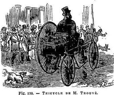
On a tricycle of English construction, very heavy (55 Ibs.) M.Trouvé had one of his motors below the axle of the wheel which communicated the movement through a Vaucanson chain. The motor was powered by six secondary cells or accumulators of the Plante type, he built with such perfection. The total weight of the vehicle, batteries, engine and rider included, up to 160 kilogr., and the effective force of the motor 7 kilogrammetres. Nevertheless, the tricycle has set itself in motion, once we had established electrical communication and traveled several times in both directions, the Rue de Valois, the speed of a good car. The experiment lasted one hour and a half (fig.138) and is conclusive.
file.php

The second application of M.Trouvé is no less happy than the first, we want to talk about his electric boat with which he went up very easily during the course of the Seine in Paris, with three people in his boat. The experiments were conducted on the Seine, the Pont-Royal, 26,27,28 May and 3 June 1881, in the presence of the highest scientific and political notables, left nothing to be desired (fig. on page 361). Each trip was to go up the Seine from the dock and return, located just below the Pont-Royal to the Pont des Arts, then dropped back to starting point. The time for each trip turned out exactly the same from first to last, which shows sufficient consistency of the pile and safety of the Trouvé motor, each experiment included a couple of trips that lasted between one hour and a half and two hours. The engine was powered by two bichromate of potassium batteries of six cells each. The velocities obtained per second, measured precisely by means of a log, were 1m,50 or 4,500 meters per hour, with a propeller with three branches, up the stream of the Seine, and 2m,50 or 8,640 meters per hour, down river. This new application of electricity, made entirely practical, is very studied, the more one examines the details, the more we realize that nothing has been left to chance, since the rudder, engine, propeller, to the disposition of the batteries, everything points to a great accomplishment.

(Figure from page 361:)
Pg361.jpg


So, only six cells on the trike (about 12V w/enough Ah's for 1.5hr run-time), and yah a Vaucanson chain on the trike too. Confirms also Gustave made his own cells, and although they are described as "Plante" lead-acid, I'm pretty sure this is plante with a small "p"... that "plante" at this time referred to the fact they were true secondary batteries and not any of the wide variety of other cells that folks were experimenting with that were all primary cell chemistries. That his "plante" cells for his etrike were Faure varient.

tks
LoCK
 
From earlier:
Lock said:
Here we go... from The Popular Science Monthly 1881 May to October:
NOTES
M.G.Trouve has applied two of his electric motors to an English tricycle, with a gratifying success in making it go. The machines were each fed by three of the accumulators which he uses in his polyscope...
I'd guessed that the reference there to "two" motors was to his twin-bobbin motor... Now I realize it says "...each fed by three of the accumulators..." Makes me think he split his pack - two 6V batteries of three cells each... Speed control? I've read about field weakening for sepex motors, but bobbin weakening??? Doesn't sound right "magnetically"... The twin bobbins are coupled mechanically via the gearing, so would a "dead" bobbin still play nice? Wouldn't it start generating? Hmmmm...

Lock
 
TylerDurden said:
They seem to have made quite a few configurations of drivetrain.

Ya can say that again TD... :)

Found another Rotary in a museum in France:
Coventry_Rotary_1878.jpg

... identified as 1878.

So, so far, the original Coventry Lever in 1877-1878

Then a chain drive, but NOT a *center* chain drive in 1878...

The Imperial War Museum identified theirs as about 1884 and it's a center drive with "modern" pedals and chain.

Then the guy in the tintype of uncertain vintage, with the same side-chain setup as this latest pic, except unlike all the other images here so far his Coventry is *left-handed*... the steering handle is at his left hand, all the other trikes steer with the right. (It's possible the image is reversed too.)

Then the tandem one in the Davis CA museum identified as 1879 that has *both* the center drive and the side-chain... Pretty sure it is a "his-and-hers", where the ladies preferred not stradding a center chain, and the guarded side chain meant they were less likely to get a long skirt caught in the chain. This couples tandem (if true) puts the guy permanently in the position of "back seat driver" which is sort of interesting :mrgreen:

In this latest pic (Year 2 of production maybe) they have already dropped the bench seat but it still has a small back rest.

For Gustaves trike and every image of the Coventry Lever the bar that joins the two steering wheels is basically straight. For all the others pictured (*except* Tintype-Guy) the bar has two pronounced "knuckles" where both ends drop lower at the wheels.

Looks like they went to a smaller wheel-size in Year 2 and bent the bar to compensate.

Tintype-Guy has a more-or-less straight bar, and his seat looks really highly elevated off the cross-bar of the bike. I'm beginning to think he's not riding a Starley-designed Coventry at all, just somebuddys bad copy!

Anyway, this latest pic may be closest to "Lever-vintage" and shows off some of the details nicely like the height-adjustments for the handles plus the foot rests/pegs to help mount/dismount.

Lock

PS... One more pic. Published in "La Nature" in 1885 (so unsure of the model year exactly) of the "Photo-Tricycle":


Kinda demonstrates the cargo-carrying capabilities for the trike. :)
About 8 years into production, and still with the side chain, and, looks like, a back rest...
 
Found an article from La Nature, reprinted in Scientific American
1881 July 9

The Electric Boat

Mr.G.Trouve has just constructed an electric motor specially adapted to be used in a row boat or canoe. He made his first public experiment on the 26th of May, in Paris on the Seine, in the presence of MM.Berger, Commissioner General of the Exposition Universelle d'Electricite, Antoine Breguet, editor of the Revue Scientifique, and numerous other spectators, who were greatly astonished to see the boat moving against the current without oars or the smoke generally inseparable from the steam engine.
TheElectricBoat_1881July9_Fig1.jpg
This electric motor is furnished with a Siemens armature connected by an endless chain with a screw having three paddles, and placed in the middle of an iron rudder. The motor is placed on the upper part of the rudder, so that both the motor and propeller follow the movements of the rudder.

This motor, with all its accessories, only weighed five kilogrammes, and was placed in the rear of a little barge about five meters fifty centimeters long, by one meter two centimeters in breadth, and weighing eighty kilogrammes.

In the middle of the boat were placed two secondary batteries weighing twenty-four kilogrammes. Mr. Trouve prefers two batteries, as they are more easily managed and have the advantage that they can be used either together or separately; also that in the evening one can be used for propelling and the other for lighting the boat.

The secondary piles are connected with the motor by two cords that serve both to cover the conducting wire and to work the rudder, and are furnished with handles that can be used to regulate the electric current.

This electric motor is complete in itself, and can be placed on a small boat. It is arranged in such a way that it does not interfere with the action of the boat or the use of the oars.

The ingenious inventor, before deciding on the endless chain, made various experiments with the different ways of propelling by cog-wheels by an endless screw and by friction. He found the two first too complicated and too easily clogged by the sand, branches, etc., floating in the water to be advantageously used, while the latter system, though perhaps the better, presented numerous practical difficulties. The endless chains are the best adapted for actual use, as their slower movement is more than compensated by their greater strength and regularity.

Besides her experimental trip, this electric boat has at six different times easily navigated the Seine for a distance of 200 meters. It is found that the boat, containing three persons, stemmed the current at the rate of one meter a second, and descended with a speed of two meters five centimeters. The current of the Seine at this place runs about twenty centimeters a second.

These trials are very interesting from an experimental point of view, and will, we hope, be an incentive to more important works. These will assuredly take place when the supply of electricity is more easily procured, for it cannot be denied that the present electric pile is not an advantageous arrangement, as it is difficult to mount and its power is limited.

These experiments recall those made by Jacobi in 1829 to navigate the Neva by electricity. We reproduce from the Merveilles de la Science the account of this interesting attempt, which well deserves to be called the origin of electric navigation.

The voltaic apparatus that furnished the electricity to Jacobi's motor was composed of two Grove batteries, each containing sixty-four pairs of cells, the whole covering thirty-two square feet. This furnished so powerful a current that a piece of platinum wire, 2 m. long and as thick as a piano string, was immediately healed to a red heat on being exposed to the electric current.

There was so much nitrous gas liberated by the pile that the operators were seriously incommoded, and were several times obliged to interrupt their experiment.

The spectators, who stood on the banks of the Neva, were also forced to retire on account of the suffocating odor of the liberated gas that the wind blew on to the shore.

The barge, which was made with paddlewheels, and was large enough to hold twelve persons succeeded, however, in sailing several hours on the river against both wind and tide.
—La Nature.
TheElectricBoat_1881July9_Fig2.jpg

This confirms again that Gustave was quite used to splitting the pack, perhaps mostly for convenience of handling, but the mention of using a battery for lighting is new...

And the handles. "...used to regulate the electric current."

So sounds like they were more than just "handles" after all! I wonder if "regulate" just means on/off switches... He must have had some similar switches close at hand on his trike.

Lock
 
This one's just for fun. An article from Engineering reprinted in Scientific American, October 15, 1881. It details some of the specs and results that Gaston Tissandier was getting from his prototype balloon at the 1881 Exposition...

Electricity and Ballooning.

Soon after the announcement of Faure's new accumulator of electricity the idea was thrown out by Mr.Martin Tupper in this country that storage batteries could be employed with advantage in propelling balloons. Power and not levitation was, in Mr.Tupper's opinion, the true key to the attainment of aerial travel. French aeronauts Have also given their attention to the subject, and at the recent meeting of the French Academy of Sciences M.Gaston Tissandier made a communication on it. The true solution of the problem, if it be feasible at all, appears to us to lie not in the exclusive use of levilation or electric power, but in a proper combination of both principles. This plan is that which M.Tissandier contemplates, and he points out that a propeller driven by electricity possesses advantages over other methods of movement. For example, it requires no fire, which is a dangerous element in a balloon inflated with hydrogen gas; it has a constant weight and gives off no products of combustion, and is readily manipulated.

M.Tissandier prepared a small balloon, pointed at the ends, 11 feet long by about 4 1/2 feet in diameter. Its volume was 484 gallons, and when filled with pure hydrogen gas it had an ascending force of about 4 1/2 pounds. A Trouve motor of the Siemens type weighing nearly 8 ounces was fixed to the lower part of the balloon and connected to a double-bladed screw of 18 inches diameter. With the aid of a Plante secondary battery weighing nearly 3 pounds, the screw was driven at the rate of 6 1/2 turns per second, and propelled the balloon through the air at a speed of over 3 feet per second during a space of 40 minutes. With two secondary elements weighing 1 1/2 pounds, and a screw of 21 inches diameter, a speed of 6 1/2 feet per second was maintained during 10 minutes. With three elements the speed was about 10 feet per second. M.Tissandier also measured the work done by the little dynamo-electric motor, and found it to be about 314 foot pounds with a single element and a speed of 5 turns per second; and with three elements it is about 7 foot pounds. He estimates that a dynamo-electric motor of 5 cwt. with 17 cwt. of secondary batteries will yield 6 horse power of work. This weight could be raised by a hydrogen charged balloon of 3,900 cubic yards volume, and similar to that employed in 1852 by M. Giffard, and in 1872 by M.Dupuy de Lome. It would be 131 feet long by 43 feet in diameter at the middle, and its ascending force would be about 3 1/3 tons. With all its appurtenances it would weigh from 19 cwt. to 22 cwt., and there would remain from 1 ton to 2 tons for ballast and voyagers. In calm weather it would have a speed of from 12 to 15 miles per hour, and it would be able to deviate from the line of a wind.

It is true that this result could only be obtained during a limited time, but the conditions would be greatly improved by lighter batteries and possibly by tho use of M.Faure's accumulators. While upon this subject we may also mention that M.Trouve has tried his electrically propelled boat on the upper lake of the Bois de Boulogne with a Trouve motor and a four-bladed screw about a foot in diameter. Twelve Bunsen cells of Kuhmkorff's pattern propelled the boat, containing three persons, at a speed of 10 feet per second, but this rale fell off at the end of three hours to about 9 feet per second, and at the end of five hours to 8 feet per second.—
Engineering.

This does point out that Gustave was trying different cell chemistries in his boat. I'd be surprised if the same were not true on his trike...

tks
Lock
 
Another report, in The Popular Science Monthly, Nov 1881 - Apr 1882 also copied from La Nature apparently:

M.Trouve's Electric Canoe.-"La Nature" gives the details of a series of experiments made upon the Seine, at Paris, in the latter days of May, with the electric canoe and motor invented by M.G.Trouve. The motor is composed of an improved Siemens coil, which acts through a Vaucasson chain and a Galle chain upon a three-bladed screw fitted into an opening cut out of the rudder to receive it. It is fixed to the upper part of the rudder, so that it, as well as the screw, follows all its movements. The motor employed in the experiments was composed of two coils, and, with its accessories, did not weigh more than five kilogrammes (twelve and a half pounds). It was placed in the stern of a canoe, the Telephone, which measured seventeen feet ten inches by three feet ten inches, and weighed one hundred and eighty pounds. Two cup batteries of bichromate of potassa, composed of six elements each, and weighing together sixty pounds, were placed in the middle of the canoe. They were connected with the motor by two cords, which served at the same time as envelopes for the conducting wires and as tiller-ropes, which were furnished with appurtenances for applying or shutting off the current at will. The motor is independent, and can be applied to any boat. The first experiments were made on the 26th of May, when the boat was worked for about forty-five minutes by M.Trouve and M.Tissandier, in the afternoon, and by M.Trouve and others for about the same time in the evening. A third experiment was made on the 31st of May, in the presence of M.G.Berger, commissioner-general of the Universal Electrical Exposition, M.A.Breguet, of the "Revue Scientifique," M.Hospitalier, M.Fricero, of the Russian navy, and others. The Telephone, with three persons in it, easily went up the Seine six times for a distance of 200 meters, or six hundred and fifty feet, at the rate of one metre in a second, and descended at the rate of two and a half metres in a second. Other experiments were made on the 2d of June, in the presence of the Russian Admiral Likhatchof and a number of spectators interested in science or navigation.

These experiments recall a similar attempt made on the Neva in 1839, by Jacobi. He used on the occasion two Grove batteries, each composed of sixty-four couples of zinc and platinum, and presenting a surface of sixteen square feet. The boat, propelled by paddle-wheels, and carrying twelve persons, sailed upon the river for several hours against the currant, and in spite of a violent wind; but the operation was greatly inconvenienced by the nitrous gas, which escaped in great quantities, and the spectators on the banks were obliged, by the suffocating fumes, to leave the place. Electric navigation may be considered to have originated with this experiment.

"...a Vaucasson chain and a Galle chain..." Watt the heck is THAT all about? Two chains??? "Galle" chain is this stuff:
GalleChain.png

...originally invented by Frenchman André Galle in 1829, so it was definitely around for Gustave to use, but all the other mentions have said Vaucasson... confusing.

"...motor employed in the experiments was composed of two coils..." I suppose this could refer to one stator coil plus the bobbin... and not to two bobbins... more confusion.

"...appurtenances for applying or shutting off the current at will." At least this seems to confirm the handles as on-off switches...


Lots of conflicting reports... this one in The Engineering and mining journal, Volume 31
June 18, 1881:
The Propulsion of Boats by Electricity.—The Paris correspondent of London Nature was present on Friday, May 27th, during an experiment made by M.Trouve on a small boat between Pont Royal and Pont des Arts. The boat, measuring 5 m. 50 by 1-30, and carrying three persons, obtained a mean velocity of 1 m. 30 per second, with a magneto-electric motor weighing 2 kilog., and two series of six Wollaston elements weighing 12 kilog. each. The trial lasted an hour and a half, and was interrupted by darkness. These experiments will be repeated shortly on the Bois de Boulogne lakes. The motor, which was constructed to give 8 kilogrammeters per second, did a duty which a single rower would have been unable to perform. The electro-magnetic motor was placed on the rudder, and the motion communicated to a small screw placed in the lower part by a chain. This system is not calculated to utilize the whole extent of the motive power generated by the elements, but it dispenses entirely with any alteration to the boat. This last circumstance is considered as decidedly important in popularizing the system among yachtsmen. There is not the slightest vibration felt or noise of any description heard on board.

First mention of the cells being "Wollastons"... Wollaston cell elements were zinc and copper. Bichromate of potassium cells used zinc and carbon...

Odd comment about "...This system is not calculated to utilize the whole extent of the motive power generated by the elements..."

Lock
 
This was published in the New York Times on August 29, 1881 under the title "ELECTRICAL CURIOSITIES, PLOWS, RAILWAYS, TOY BOATS, AND BALLOONS AT THE PARIS EXPOSITION.
Paris Letter to the London Times
LetterToTheTimes_1881_Aug29.jpg

One mile an hour... that sucks :) But he was motoring `round and `round that dinky pond at the Exposition... so looks like he cut power to the motor by just using one battery of three cells (6 volts.) Do series-wound motors behave this way? RPMs depending on voltage?

Found out how Tissandier was flying his balloon at least. :lol:

LocK
 
Lock said:
Do series-wound motors behave this way? RPMs depending on voltage?
Yes. Most motors do; only exception I can think of would be a synchronous AC motor, which depends on the frequency instead. (a little different from the typical hub or RC motor). Or a stepper motor.
 
amberwolf said:
Lock said:
Do series-wound motors behave this way? RPMs depending on voltage?
Yes. Most motors do; only exception I can think of would be a synchronous AC motor, which depends on the frequency instead. (a little different from the typical hub or RC motor). Or a stepper motor.
Tks AW. Really, really high Kv maybe? That bit about series motors and no-load self-destruct... eg from here:
http://zone.ni.com/devzone/cda/ph/p/id/53#toc0
When Ohm's law is applied to this circuit, you will see that when the voltage is slightly reduced, the current will also be reduced slightly. This means that the series motor will see less current as its speed is increased. The reduced current will mean that the motor will continue to lose torque as the motor speed increases. Since the load is moving when the armature begins to pick up speed, the application will require less torque to keep the load moving. This works to the motor's advantage by automatically reducing the motor current as soon as the load begins to move. It also allows the motor to operate with less heat buildup.

This condition can cause problems if the series motor ever loses its load. The load could be lost when a shaft breaks or if a drive pin is sheared. When this occurs, the load current is allowed to fall to a minimum, which reduces the amount of back EMF that the armature is producing. Since the armature is not producing a sufficient amount of back EMF and the load is no longer causing a drag on the shaft, the armature will begin to rotate faster and faster. It will continue to increase rotational speed until it is operating at a very high speed. When the armature is operating at high speed, the heavy armature windings will be pulled out of their slots by centrifugal force. When the windings are pulled loose, they will catch on a field winding pole piece and the motor will be severely damaged. This condition is called runaway and you can see why a DC series motor must have some type of runaway protection.

Hmmmm!
LocK
 
That's why often in this thread:
http://www.diyelectriccar.com/forums/showthread.php/using-forklift-motor-and-choosing-good-7598.html
you'll read people telling others to test their newfound forklift motors at no more than 12V, until they have it installed in a vehicle or otherwise loaded. ;)

Grenading a commutator is not much fun, based on the various experiences I've found told on the web here and there. :(
 
amberwolf said:
That's why often in this thread:
http://www.diyelectriccar.com/forums/showthread.php/using-forklift-motor-and-choosing-good-7598.html
you'll read people telling others to test their newfound forklift motors at no more than 12V, until they have it installed in a vehicle or otherwise loaded. ;)
Grenading a commutator is not much fun, based on the various experiences I've found told on the web here and there. :(
Holy crapolla... that thread's 101 pages and counting! ...but anything "Husted" is golden. :)

I suspect that the 12V recommendation just allows more human reaction time to shut down. Less energy supplied means the motor gets a bit restricted just from friction and drag from cooling fans etc. From here:
http://books.google.ca/books?id=fK_...ical maximum rpm&pg=PA248#v=onepage&q&f=false
SERIES-WOUND DC MOTORS - "...It also does not have any theoretical maxumin no-load speed that makes it tend to run away if the load is removed."

and here:
http://www.gizmology.net/motors.htm
In a series-wound motor, the field current is always equal to the armature current. Under no load, the torque produced by the motor results in acceleration. As speed increases, induced voltage would normally increase until at some speed it equalled the applied voltage, resulting in no effective voltage, no armature current, and no further acceleration; in this case, however, increasing speed decreases field current and strength, stabilizing induced voltage. Torque never drops to zero, so the motor continues to accelerate until it self-destructs.

and here:
http://bbs.homeshopmachinist.net/archive/index.php/t-22741.html
In theory, ignoring all mechanical considerations, the only limit to the max rpm of a series wound motor is the time it takes for the magnetic fields to propagate. That happens to be the speed of light, modified by the time constants of the circuits.

Also reading stuff like 700-800% rated torque at zero RPMs... :twisted:

So yah, "grenade" seems the operative word. Really going to need to build w/chain etc highly over-spec.

LocK
 
Rankin Kennedy was headmaster of Papa Westray school, Orkney in the 1880-1890s. In the spring of 1880 he wrote a series of pieces in the journal English Mechanic and World of Science about the design and construction of dynamo- and magneto-electric machines. Here is Part Four published April 9, 1880. This would have been very contemporary to the experiments that Gustave was doing in Paris at the time. It illustrates the thinking, and some of the materials and methods being used at the time to "home build" smaller motors:

English Mechanic and World of Science Volume 31
No.785 April 9, 1880

CONSTRUCTION OF SMALL DYNAMO AND MAGNETO - ELECTRIC MACHINES—IV.

[17111.]—The making and working of the two machines described in letters 16875 and 16957, led up to the machines which I am about to describe now, one a magneto-electric, and the other a dynamo-electric. I can recommend them for their powerful action. They require a good deal of care and mechanical skill in their construction, but the result will well repay the time and money spent on them.
EnglishMechanicAndWorldOfScience_1880Fig1.jpg

Fig. 1 is a perspective view of the magneto-electric machine, built on the very same plan as the machine first described in these letters, the only difference being in the armature and pole-pieces. The armature is of the Gramme type, but owing to its great length it is made in four segments. Fig. 2 and Fig. 3 end view, with sizes. Fig. 4 shows the armature complete, the four segments being bound together, after being carefully fitted, by three brass rings. Fig. 5, the wire is wound on the two channels on the segments, as shown in the cross section; three layers, No.20, 16, or 18, according to the character of current wanted; No.20 would give a current somewhat similar to six or eight small Bunsens in series No.18, a larger current with smaller E.M.F. After the wire is wound on the segments they are fixed together by a temporary wire being wound around them; the brass rings are then to be turned out to such a size that, when they are heated to redness just visible in the dark, they will slip over the armature; they may then be cooled as quickly as possible; they will then contract and bind the segments firmly together. I have the armature with flat rings, but Fig. 5 will be stronger.

The armature is then mounted on a spindle. Fig.6, 7/8in. diameter rod-iron, when turned up true will do; two boxwood or ebonite plugs turned to fit tightly into each end of the armature, and bored to slip over the rod as at PP, suffice to hold the armature in its place. C is the commutator, like that described in III. letter, with eight No. 12 or 10 copper wires run through it; the ends of the wire sections are brought out two and two, as shown in cross section, two ends being joined to eacn wire in the commutator; the collecting springs may be slipped between the magnets, insulated, of course.

The segments of the armature are made of soft malleable cast-iron.

The pole-pieces 12in. long are made of soft cast-iron or malleable cast-iron. These pole-pieces must have recesses cut in their faces to clear the rings on the armature, or a space is left between the magnets as at S (Fig. 7).

As I stated before, the magnets may be made of fine hard cast iron, 8in. long in the straight part of the leg, 1/4in. thick, 1 1/2in. broad, 3 3/8in. between the legs. Before getting them cast, a slip of wood should be made 6in. long, 1in. broad, 1/2in. thick, and sent to the founder; get a casting off this of his hardest metal, and try it as to how far it may be magnetised, and how long it may keep it. By trying a few qualities of iron in this way a suitable one may be got; the addition of a handful of prussiate of potash to the metal, just before it is poured out of the pot, greatly improves it as a magnet cast ready to shape. These magnets might perhaps be cast of steel; the spindle may run between centres or in brass blocks.

This machine can be driven easily by one hand the armature going at 1,000 to 1,200 revolutions a minute, and with No. 18 wire on the armature, gives about eight vebers per second through total R of about .77 ohm.

Fig. 7 is a perspective view of the dynamo-machine with the same armature, which for this machine, should be wound with two layers for the field-magnets, m.m.m., coils No. 18, the ends of this layer being brought out to commutator just as in the above machine; other two or three layers, according to fineness of wire, may then be laid on and brought out to a commutator at the other end of the shaft for external work; the base of the machine is one casting, and forms part of the field-magnets. The field-magnets m.m. are soft iron, 2 3/8in.,3in. broad, 1/2in. thick, 6 1/2 in. long, coiled with five layers of No. 14 cotton-covered wire.

I shall sketch the details of this machine in my next.

Rankin Kennedy.
Papa Westrey, Orkney.

Haven't noted any "bands" illustrated on Gustaves armatures... Thinkin' he went with the approach to armature construction mentioned earlier where flat disks are cut from sheet and threaded onto the axle to build his "drum"... Useful to see the discussion about wire sizes, field versus armature...

Lock
 
There were a series of articles published in 1879 in the journal ANNALES INDUSTRIELLES on the subject MOTEURS ET GENERATEURS... A lot of it on the relative merits of steam versus compressed air and electricity etc for the transmission of mechanical power.

This from June 22, 1879 (usual poor translation from the original French:
Although very simple in principle, the application of electricity to different devices used in the industry forced to solve a host of very important matters of detail which have required considerable studies.

First, it was in a lot of cases, finding a controller that could limit the speed variations resulting from a change either in the amount of power, either in the job. This device is particularly essential whenever a single machine to provide power to multiple devices operating alternately or simultaneously.

This difficulty was resolved in a very happy by MM. Christian and Felix. Their controller is shown in Figure 2.
ANNALES_INDUSTRIELLES_1879Jun22.jpg
At one end of the shaft of the machinery itself is a moderator at balls with a mission to move forward or backward sweep collector current. This broom moves on a ground (here is a single coil) introduced as a resistance in the circuit.

At normal speed, giving the machine its full force, the brush and the regulator are in the position indicated in the figure, the current flows directly from the finish line in the brush, much of the mass of resistance being outside. - But if labor goes down, the speed increases, the blade moves toward the left and introduced during a larger amount of mass resistance, and then reducing engine power, speed increasing.

It is important to note here that this mass thus introduced does not absorb the engine work, but to reduce the amount of work taken on the engine. This work in effect is even smaller than the circuit resistance is greater, and becomes quite zero (excluding passive resistance, of course) when power is interrupted. We can therefore say that the work borrowed the engine is still substantially proportional to that carrying the receiver.

Haven't found any indications that Gustave was using any speed control or governor on his "grenade-style" series-wound motors (other than adding/subtracting cells in the pack, and looks like on/off switches) so it was nice to see the potentiometer illustrated here.

Well, turns out variable resistors had been around almost 40 years already (Poggendorff, Wheatstone.) So mighta been another "tool" for Gustave to use...

Tks
Lock
 
Back
Top