
dirty_d
10 kW
ok, so im going to start designing a sensorless brushless motor controller, but before i even start drawing any schematics im going to make sure i understand every part of its operation, so far this has been the most troublesome part. it seems there are so many different ways to do the zero cross detection, some using the ADC to sample the voltage of the floating phase and a reconstructed neutral point and watch when they cross, either during PWM on or off, or using analog comparators to trigger external interrupts on the MCU like hall sensors would. this controller would mainly be for the big RC motors, they are pretty much all high rpm and high pole count, so each commutation step is extremely short.
the motor im going to test with is that 130Kv HXT motor, im not sure how many poles it has but ill guess at 12 for now, at 33V and a no load speed of 4300rpm, each commutation step at max speed would only be 387 microseconds. the fastest the MCU im using can take an ADC sample is once every 68 microseconds. so during each commutation step, only 5 voltage samples could be taken, that doesn't seem like it would be anywhere near high enough resolution to accurately determine the zero crossing point. so it seems the only solution for finding the zero crossing point would be to use three analog comparators with the inputs being half the voltage between the two powered phases, and the floating phase. when the backemf in the floating phase crosses zero the output of the comparator will change from low to high or vice versa and trigger an interrupt on the MCU.
there needs to be a low-pass filter on all of the inputs to help with the PWM noise, it seems like it would be best solution would be to use a comparator that would be able to take the full voltage that will be seen across the phases, that way you don't have to use voltage dividers and attenuate an already weak signal that you have at low rpm. i think the comparator would only actually have to be rated at half the largest voltage across the phases would be since there is already a divider across each of the phases to get half the voltage to compare against. the inputs directly from each phase wire for when that phase is floating would see the full voltage when that phase was powered though, so it could be clamped with a zener diode i believe and not do any harm to when that is the phase that is floating.
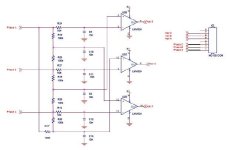
i found a nice schematic in one of the AVR appnotes, it uses LMV824s, they are only rated for 5.5V though, im thinking maybe LM324s could be used instead since they can be used up to 32V, the thing im not sure about is the bandwidth of them, the lmv824 is 5MHz, and the lm324 is 1MHz, i don't know if this is critical to this circuits operation. also it said the delay on the comparator output after the zero crossing is about 125 microseconds from the low pass filters, how do you calculate the delay of a low pass filter?
if anyone could help out or if you know any other better methods of finding the zero crossing point that would be awsome.
the motor im going to test with is that 130Kv HXT motor, im not sure how many poles it has but ill guess at 12 for now, at 33V and a no load speed of 4300rpm, each commutation step at max speed would only be 387 microseconds. the fastest the MCU im using can take an ADC sample is once every 68 microseconds. so during each commutation step, only 5 voltage samples could be taken, that doesn't seem like it would be anywhere near high enough resolution to accurately determine the zero crossing point. so it seems the only solution for finding the zero crossing point would be to use three analog comparators with the inputs being half the voltage between the two powered phases, and the floating phase. when the backemf in the floating phase crosses zero the output of the comparator will change from low to high or vice versa and trigger an interrupt on the MCU.
there needs to be a low-pass filter on all of the inputs to help with the PWM noise, it seems like it would be best solution would be to use a comparator that would be able to take the full voltage that will be seen across the phases, that way you don't have to use voltage dividers and attenuate an already weak signal that you have at low rpm. i think the comparator would only actually have to be rated at half the largest voltage across the phases would be since there is already a divider across each of the phases to get half the voltage to compare against. the inputs directly from each phase wire for when that phase is floating would see the full voltage when that phase was powered though, so it could be clamped with a zener diode i believe and not do any harm to when that is the phase that is floating.
i found a nice schematic in one of the AVR appnotes, it uses LMV824s, they are only rated for 5.5V though, im thinking maybe LM324s could be used instead since they can be used up to 32V, the thing im not sure about is the bandwidth of them, the lmv824 is 5MHz, and the lm324 is 1MHz, i don't know if this is critical to this circuits operation. also it said the delay on the comparator output after the zero crossing is about 125 microseconds from the low pass filters, how do you calculate the delay of a low pass filter?
if anyone could help out or if you know any other better methods of finding the zero crossing point that would be awsome.


 Or a busted one maybe even?