zombiess
10 MW
I'm attaching high quality big pics for your viewing pleasure in the following 2 zip files. Please download them for reference.
View attachment Sevcon part1.zip
View attachment Sevcon part2.zip
Warranty is now VOID

I acquired a Sevcon controller and decided to rip it apart and take a look and see what I can learn about it. I also want to play arm chair quarterback")
I've been puzzled how they can deliver high current without using bus bars which is tricky when looking to manufacture a high current product.
This controller is rated for 96-120V, 540A for 10 sec, 450A for 2 mins and 180A 60 mins. It has 10 MOSFETS in parallel per phase so the most it will see in boost mode is 54A per MOSFET which is reasonable for 10 seconds. All these rating could probably be a little longer if the controller was built with bus bars vs using the PCB layers to carry all the high current. Note that even with 10 parallel MOSFETs it's only rated to do 18A each. This is a reasonable continuous rating and the controller has the biggest heat sink of any controller I have on hand (by a significant margin) including my own designs.
Ranked by heat sinks thermal mass/cooling ability only from biggest to smallest the controllers are as follows
1. Sevcon (lots of mass and surface area)
2. Sabvoton (lots of mass and surface area + finned case)
3. Xie Chang (EB324, small mass, OK surface area + finned case)
4. Kelly (not so great thermal path + finned case)
5. Adaptto Max-E (very tiny heat sink bar, little surface area and no fins)
The Kelly and the Xie Chang 24 FET are pretty close, the older EB2xx 24/36 FET controllers are probably tie with the Kelly on heat sinking. Adaptto has a very small heat sink bar and MOSFETs on both sides and no fins on the case. It could certainly use a more heat sink, but the trade off would be a larger controller.
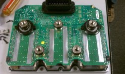
Pic 01 and 02
These are shots of the front and back side of the PCB, board is multi layers as can be seen from the dark breaks between the phases. The battery current looks to be run on the internal layers. My guess is there are multiple paralleled layers being used to carry the current. Board is probably uses extra thick copper layers. Entire board is conformal coated with a soft plastic like coating, no chipping like cheap conformal coating does.
I would like to see one of these PCBs under FLIR camera while operating to see where the hot spots are and how quickly things heat up. I'm surprised that they can obtain a 60min run at 180A, that's pretty impressive. The phase output has a very wide trace, looks to be about 50mm wide and I'm guessing runs through several layers. I can see the top an bottom of each phase connects the high side drain to the low side source, not sure how many or what is going on with the internal layers.
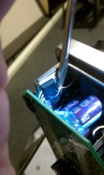
The caps are Nichicon CS series electrolytic, 100uF, 160V each and there are 42 of them for a total of 4200uF DC link. Rated for 8000-10,000hrs at 105C. Not a big fan of their location due to being in a high heat area, but there isn't much room to place them elsewhere and they are rated for long life at 105C which is above the recommended operating temperature of 80C for MOSFETs. This was most likely a cost saving decision for manufacturing.
Capacitor Datasheet
http://www.google.com/url?sa=t&rct=j&q=&esrc=s&source=web&cd=2&cad=rja&uact=8&ved=0CCUQFjAB&url=http%3A%2F%2Fwww.nichicon.co.jp%2Fenglish%2Fproducts%2Fpdf%2Fe-cs_pz.pdf&ei=vR-_VIPNMJfhoATWkYC4DQ&usg=AFQjCNHNKkrnvKuvBjYzZJrJ30X4revKxA&sig2=qy7Xld_15rB_yZabNvfYnA&bvm=bv.83829542,d.cGU
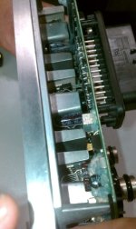
Pic 03 and 04
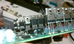
These are the MOSFET mounts that hold to the heat sinks. MOSFETs are held by very firm spring pressure only which often provides better thermal contact then using screws. Note that the phase current is controlled by 2 phases only.
Pic 05
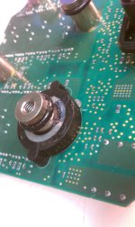
Mounting posts for battery and phase outputs going through the board and contacting all layers. Multiple vias and 3 large vias are visible around the posts.
Pic 06, 07, 08
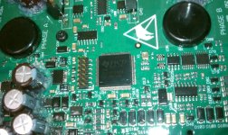
This is the digital side. I'm not going to look into this too much beyond the processor which I talk about in Pic 11.
Pic 09
I'm not exactly sure what these do, I thought they might be cap bleed resistors for life safety, but they are only 6.6 ohms each which would mean they would dissipate way too much current and they look like 3W rated. They are not directly connected to the DC Link caps.
Pic 10
This is one of two temp sensors placed into the heat sink.
Pic 11
The Gen 4 uses a FOC running on a TI C2000 series DSP, a TMS320F2811PBKA. This is a nice processor and it can run up to 150MHz, 12 bit ADC and all the other typical goodies TI DSP's come with like lots of IO pins >50. This is not an Instaspin processor so the control algorithm is something they rolled themselves or possibly based off something from TI. TI has done some amazing stuff with motor control and then they give it away for free! If you haven't guessed by now, I love the TI DSP family and Texas Instruments. I believe TI is becoming market leader in motor / inverter tech and I'm not alone in thinking this. The shear volume of stuff TI gives away to developers is staggering. It's information overload. I'll get off TI's nut sack and back to the Sevcon.
Datasheet
http://www.ti.com/general/docs/lit/getliterature.tsp?genericPartNumber=tms320f2812&fileType=pdf
Pic 12,13,14
This is an interesting find, it's a IR21094S half bridge gate driver. At first glance I wasn't sure why they chose this driver as it's not exactly strong or fast with a 750ns/200ns on/off times and very low current. Then I was able to see the part number on another mystery part I suspected was another gate driver acting as a boost stage. The IR21094S looks like it is triggering a TI UCC27324 4A driver. I'm not sure if Sevcon is using negative voltage bias or has Miller clamp. I'd have to power it up to find out and I don't have a harness, cable or software. The controllers are known to be reliable. I see some SMD transistors on each gate drive so they are doing something.
Datasheets
IR2109S
http://www.google.com/url?sa=t&rct=j&q=&esrc=s&source=web&cd=1&ved=0CB4QFjAA&url=http%3A%2F%2Fwww.irf.com%2Fproduct-info%2Fdatasheets%2Fdata%2Fir2109.pdf&ei=BSK_VISaB4ysogT8x4KoCA&usg=AFQjCNGP_F8gQt18eycQa7xTg7hpC10LQw&sig2=eFA2n2RC8Bkj8QtSr7QovA
UCC27324
http://www.ti.com/general/docs/lit/getliterature.tsp?genericPartNumber=ucc27324&fileType=pdf&keyMatch=27324&tisearch=Search-EN
Pic 15
This is a shot of the gate drive connecting to the MOSFET. They have a 22ohm resistor on each gate. There is also a Gate to Source capacitor with a 2 ohm resistor in series with it. I was unable to get a good measurement of it's value.
Pic 16
The power stage is made of 10 parallel Infineon OptiMOS IPP075N15N 150V MOSFETs. These are rated at 7.5mOhm RDSon and are rated at 93A with the case temp at 100C. The gate charge is a max of 93nC making them fairly easy to drive. These are comparable specs to the IRFB4115 we are familiar with with a slightly lower RDSon. I'm not familiar with Infineon MOSFETs myself. I would be interested in seeing how well the Vgs(th)/Miller Plateau matches when purchasing 500 of them. The IRFB4115's have a pretty wide spread when compared to lower voltage IRF devices such as the IRFB4110 which group much more closely.
This is of course more than the legs will support so the 53A 10 sec burst is reasonable and leaves plenty of overhead. I suspect the PCB being the primary current carrier is the limiting factor.
Datasheet
http://www.google.com/url?sa=t&rct=j&q=&esrc=s&source=web&cd=1&ved=0CCEQFjAA&url=http%3A%2F%2Fwww.infineon.com%2Fdgdl%3FfolderId%3Ddb3a304313b8b5a60113cee7c66a02d6%26fileId%3Ddb3a304319c6f18c0119cd76cc527ab6&ei=Eyu_VJSUGpfboATiq4GoBg&usg=AFQjCNEBAGJRhhTbZqvK7nbR34AG5e0HuQ&sig2=CPGENPJKcugj1LLWMQuiiw&bvm=bv.83829542,d.cGU
Overall this is as you would expect for the price, a quality mass produced controller with very flexible tuning options. It's almost impossible to compare this to something like a one off DIY/ low volume production controller we try to build on this site where we are not constrained by budget or difficulty in assembly. Mass production is an entirely different game.
I hope you enjoyed or learned something useful from this tear down and my arm chair quarterback analysis. I tried to keep the review as neutral as I can.
View attachment Sevcon part1.zip
View attachment Sevcon part2.zip
Warranty is now VOID
I acquired a Sevcon controller and decided to rip it apart and take a look and see what I can learn about it. I also want to play arm chair quarterback
I've been puzzled how they can deliver high current without using bus bars which is tricky when looking to manufacture a high current product.
This controller is rated for 96-120V, 540A for 10 sec, 450A for 2 mins and 180A 60 mins. It has 10 MOSFETS in parallel per phase so the most it will see in boost mode is 54A per MOSFET which is reasonable for 10 seconds. All these rating could probably be a little longer if the controller was built with bus bars vs using the PCB layers to carry all the high current. Note that even with 10 parallel MOSFETs it's only rated to do 18A each. This is a reasonable continuous rating and the controller has the biggest heat sink of any controller I have on hand (by a significant margin) including my own designs.
Ranked by heat sinks thermal mass/cooling ability only from biggest to smallest the controllers are as follows
1. Sevcon (lots of mass and surface area)
2. Sabvoton (lots of mass and surface area + finned case)
3. Xie Chang (EB324, small mass, OK surface area + finned case)
4. Kelly (not so great thermal path + finned case)
5. Adaptto Max-E (very tiny heat sink bar, little surface area and no fins)
The Kelly and the Xie Chang 24 FET are pretty close, the older EB2xx 24/36 FET controllers are probably tie with the Kelly on heat sinking. Adaptto has a very small heat sink bar and MOSFETs on both sides and no fins on the case. It could certainly use a more heat sink, but the trade off would be a larger controller.
Pic 01 and 02
These are shots of the front and back side of the PCB, board is multi layers as can be seen from the dark breaks between the phases. The battery current looks to be run on the internal layers. My guess is there are multiple paralleled layers being used to carry the current. Board is probably uses extra thick copper layers. Entire board is conformal coated with a soft plastic like coating, no chipping like cheap conformal coating does.
I would like to see one of these PCBs under FLIR camera while operating to see where the hot spots are and how quickly things heat up. I'm surprised that they can obtain a 60min run at 180A, that's pretty impressive. The phase output has a very wide trace, looks to be about 50mm wide and I'm guessing runs through several layers. I can see the top an bottom of each phase connects the high side drain to the low side source, not sure how many or what is going on with the internal layers.
The caps are Nichicon CS series electrolytic, 100uF, 160V each and there are 42 of them for a total of 4200uF DC link. Rated for 8000-10,000hrs at 105C. Not a big fan of their location due to being in a high heat area, but there isn't much room to place them elsewhere and they are rated for long life at 105C which is above the recommended operating temperature of 80C for MOSFETs. This was most likely a cost saving decision for manufacturing.
Capacitor Datasheet
http://www.google.com/url?sa=t&rct=j&q=&esrc=s&source=web&cd=2&cad=rja&uact=8&ved=0CCUQFjAB&url=http%3A%2F%2Fwww.nichicon.co.jp%2Fenglish%2Fproducts%2Fpdf%2Fe-cs_pz.pdf&ei=vR-_VIPNMJfhoATWkYC4DQ&usg=AFQjCNHNKkrnvKuvBjYzZJrJ30X4revKxA&sig2=qy7Xld_15rB_yZabNvfYnA&bvm=bv.83829542,d.cGU
Pic 03 and 04
These are the MOSFET mounts that hold to the heat sinks. MOSFETs are held by very firm spring pressure only which often provides better thermal contact then using screws. Note that the phase current is controlled by 2 phases only.
Pic 05
Mounting posts for battery and phase outputs going through the board and contacting all layers. Multiple vias and 3 large vias are visible around the posts.
Pic 06, 07, 08
This is the digital side. I'm not going to look into this too much beyond the processor which I talk about in Pic 11.
Pic 09
I'm not exactly sure what these do, I thought they might be cap bleed resistors for life safety, but they are only 6.6 ohms each which would mean they would dissipate way too much current and they look like 3W rated. They are not directly connected to the DC Link caps.
Pic 10
This is one of two temp sensors placed into the heat sink.
Pic 11
The Gen 4 uses a FOC running on a TI C2000 series DSP, a TMS320F2811PBKA. This is a nice processor and it can run up to 150MHz, 12 bit ADC and all the other typical goodies TI DSP's come with like lots of IO pins >50. This is not an Instaspin processor so the control algorithm is something they rolled themselves or possibly based off something from TI. TI has done some amazing stuff with motor control and then they give it away for free! If you haven't guessed by now, I love the TI DSP family and Texas Instruments. I believe TI is becoming market leader in motor / inverter tech and I'm not alone in thinking this. The shear volume of stuff TI gives away to developers is staggering. It's information overload. I'll get off TI's nut sack and back to the Sevcon.
Datasheet
http://www.ti.com/general/docs/lit/getliterature.tsp?genericPartNumber=tms320f2812&fileType=pdf
Pic 12,13,14
This is an interesting find, it's a IR21094S half bridge gate driver. At first glance I wasn't sure why they chose this driver as it's not exactly strong or fast with a 750ns/200ns on/off times and very low current. Then I was able to see the part number on another mystery part I suspected was another gate driver acting as a boost stage. The IR21094S looks like it is triggering a TI UCC27324 4A driver. I'm not sure if Sevcon is using negative voltage bias or has Miller clamp. I'd have to power it up to find out and I don't have a harness, cable or software. The controllers are known to be reliable. I see some SMD transistors on each gate drive so they are doing something.
Datasheets
IR2109S
http://www.google.com/url?sa=t&rct=j&q=&esrc=s&source=web&cd=1&ved=0CB4QFjAA&url=http%3A%2F%2Fwww.irf.com%2Fproduct-info%2Fdatasheets%2Fdata%2Fir2109.pdf&ei=BSK_VISaB4ysogT8x4KoCA&usg=AFQjCNGP_F8gQt18eycQa7xTg7hpC10LQw&sig2=eFA2n2RC8Bkj8QtSr7QovA
UCC27324
http://www.ti.com/general/docs/lit/getliterature.tsp?genericPartNumber=ucc27324&fileType=pdf&keyMatch=27324&tisearch=Search-EN
Pic 15
This is a shot of the gate drive connecting to the MOSFET. They have a 22ohm resistor on each gate. There is also a Gate to Source capacitor with a 2 ohm resistor in series with it. I was unable to get a good measurement of it's value.
Pic 16
The power stage is made of 10 parallel Infineon OptiMOS IPP075N15N 150V MOSFETs. These are rated at 7.5mOhm RDSon and are rated at 93A with the case temp at 100C. The gate charge is a max of 93nC making them fairly easy to drive. These are comparable specs to the IRFB4115 we are familiar with with a slightly lower RDSon. I'm not familiar with Infineon MOSFETs myself. I would be interested in seeing how well the Vgs(th)/Miller Plateau matches when purchasing 500 of them. The IRFB4115's have a pretty wide spread when compared to lower voltage IRF devices such as the IRFB4110 which group much more closely.
This is of course more than the legs will support so the 53A 10 sec burst is reasonable and leaves plenty of overhead. I suspect the PCB being the primary current carrier is the limiting factor.
Datasheet
http://www.google.com/url?sa=t&rct=j&q=&esrc=s&source=web&cd=1&ved=0CCEQFjAA&url=http%3A%2F%2Fwww.infineon.com%2Fdgdl%3FfolderId%3Ddb3a304313b8b5a60113cee7c66a02d6%26fileId%3Ddb3a304319c6f18c0119cd76cc527ab6&ei=Eyu_VJSUGpfboATiq4GoBg&usg=AFQjCNEBAGJRhhTbZqvK7nbR34AG5e0HuQ&sig2=CPGENPJKcugj1LLWMQuiiw&bvm=bv.83829542,d.cGU
Overall this is as you would expect for the price, a quality mass produced controller with very flexible tuning options. It's almost impossible to compare this to something like a one off DIY/ low volume production controller we try to build on this site where we are not constrained by budget or difficulty in assembly. Mass production is an entirely different game.
I hope you enjoyed or learned something useful from this tear down and my arm chair quarterback analysis. I tried to keep the review as neutral as I can.