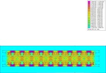
Simple axial flux Torus motor

IanFiTheDwarf said:
This comes from having nothing for the end magnets to interact with on one side, so all of their field is going in one direction. I presume that as the gap between the magnets decreases they interact more with each other. As you can’t simulate a circle in this plane or an infinite length try adjusting the size of the end magnets until the flux lines from the next magnet split evenly left and right.

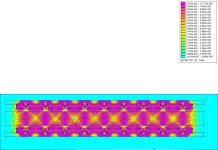
Many thanks for that suggestion- I've reduced the width of the outer magnets by half and the flux distribution is now behaving as expected :D :D :D in the attached v4 FEMM

Now all I need to do is sort out this rotor back iron saturation and I should be there!

Cheers
Mark
 

Attachments

  • Torusv4 N45.jpg
    Torusv4 N45.jpg
    142.4 KB · Views: 201
IanFiTheDwarf said:
. You have talked about your spiral wound laminate core but how are you going to make the stator teeth?
Are you planning on three complete sets of stator with two steel backed rotors for the three phases or are you going to use both sides of the magnets that are between two stators without iron backing and only have iron on the end rotors?

For this motor I'm going for a slotless back to back winding (Gramme's winding wired up as AcBaCb repeated 8 times for 48 coils, 16 per phase) on a single laminated stator with outer rotors either side...thought it best to refine this before moving onto multiple stator designs :D or maybe consider other options for the stator. The segmented armature in Mile's axial flux design has got me thinking about weight saving and improved flux concentration!!

Cheers

Mark
 
That's distance is incredible on a DIYer :!: :!: - if I manage a tenth of that I would be very pleased! Stainless steel bolts it is - this motor is destined for a mid-drive and I don't need anything "getting messy" as its spinning between my legs!!

Cheers

Mark
 
Okay, last try with FEMM this evening. Having resolved the un-even flux distribution in V4 I was seeing a high level of saturation in the iron rotors, peaking above 1.3T (if I'm reading the scale correctly?) with .6 or .7T in the airgap.

After playing around with inserting 5x5x25mm magnets between the wedge magnets I now have about .75 across the rotor, airgap and stator (see V5 attached) - I'm guessing that this would be an ideal distribution ? Only downside I need to get hold of another 32 magnets :( but before splashing out can anyone comment if this is a good direction to go ?

Cheers

Mark
 

Attachments

  • Torusv5 N45.jpg
    Torusv5 N45.jpg
    146.5 KB · Views: 201
hillma said:
Okay, last try with FEMM this evening. Having resolved the un-even flux distribution in V4 I was seeing a high level of saturation in the iron rotors, peaking above 1.3T (if I'm reading the scale correctly?) with .6 or .7T in the airgap.
1.38T is fine. Up to 1.7T should be fine....
 
Thanks Miles, thought I needed to keep below 1T so that is excellent news - no extra magnets required (though I was surprised by the impact the additional magnets made to the flux intensity in the back iron but happy to save the £40ish !)

Hopefully the build will start this weekend!

Cheers

Mark
 
Back
Top